Magnum 4A Control Wiring and Adjustment Manual www.NabcoEntrances.com
Part #C-00084 Rev. 9-09-16
3-8 Magnum 4A Board Terminals
Table #-1
Pole Wire Harness Circuit Description
1 Aux Pwr X
X Sensor must not exceed 0.5 amp current draw.
X If Sensor exceeds 0.5 amp current draw Fuse (F1) will trip. A
separate power supply must be used.
Orange
Terminal X
X
• Stop door during opening
• Prevent door from moving when door is fully closed
X
4 White X
on pull side of door.
X
• Prevent door from opening if already closed
•
X
5 Red
6 Activation
door is activated.
Table #-2
Pin Wire Circuit Description
1 Orange
Red
4
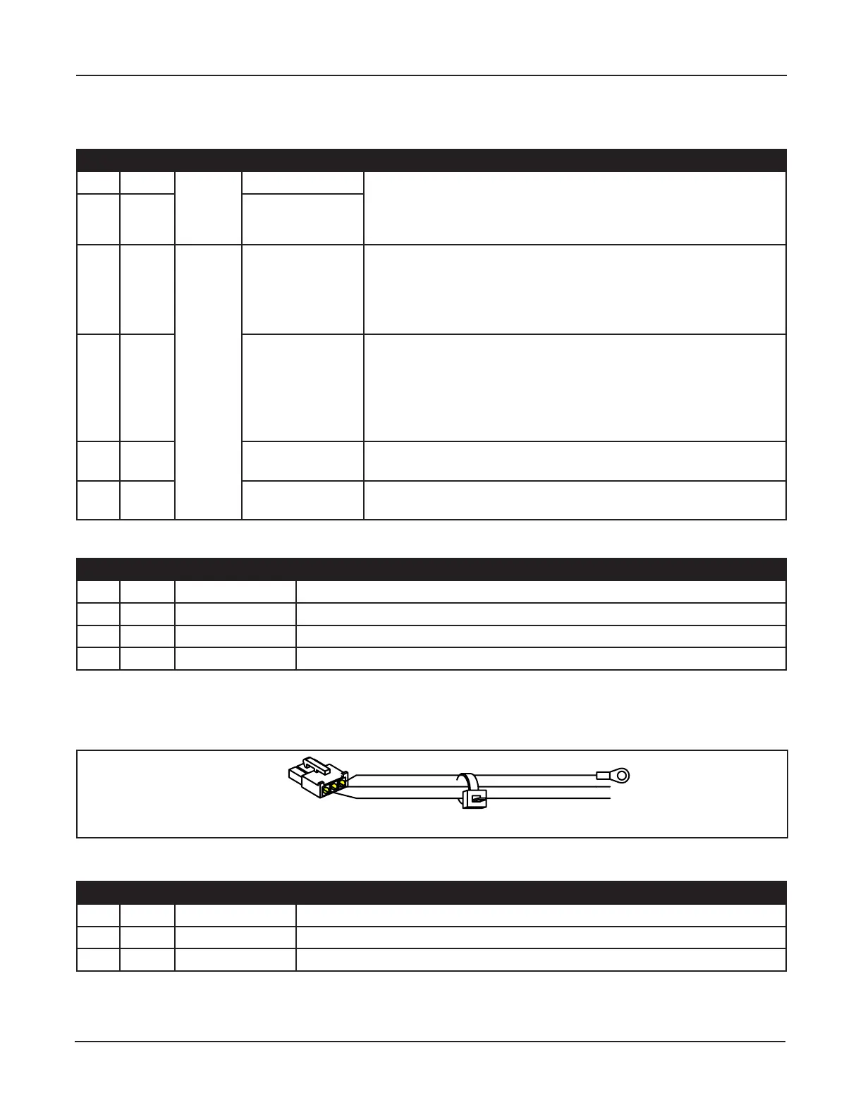
Power Harness
.
Figure 3-3
DN 0606
1
Table #-3
Pin Wire Circuit Description
1 Green Incoming Ground wire
White Incoming Neutral wire
 Loading...
