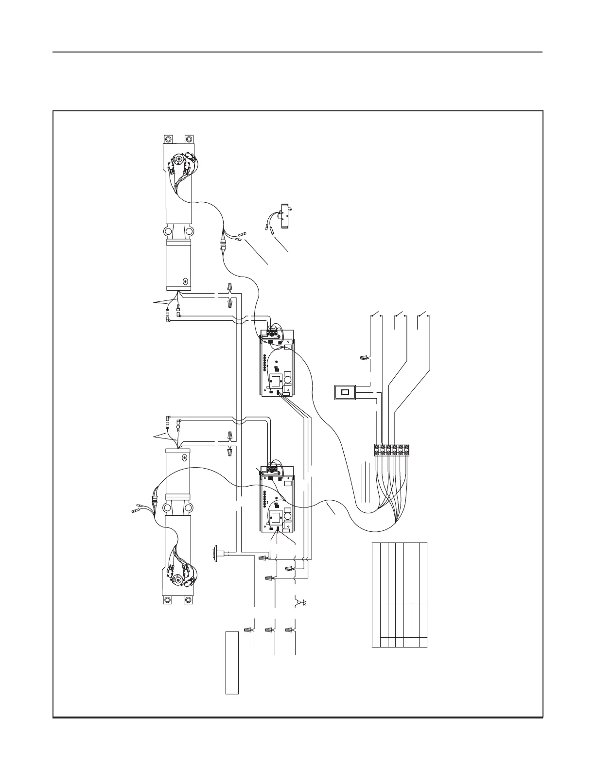
7-20 Wiring Diagrams (General)
Magnum 4A Control Wiring and Adjustment Manual www.NabcoEntrances.com
Part #C-00084 Rev. 9-09-16
DN0568
ORANGE
VIOLET
WHITE
RED
BLACK
BROWN
6
5
4
3
2
1
MAGNUM CONTROL BOARD
BLACK
RED
BLACK
BLACK
BLACK
GREEN
WHITE
120 VAC "HOT"
120 VAC "NEUTRAL"
SERVICE GROUND
MINIMUM 5 AMPERE SERVICE
PER OPERATOR
BLACK
GROUND
RED
WHITE
BLACK
TO TERMINAL #5
TO TERMINAL #5
GREEN
RED & BLACK
BLACK
RED & BLACK
BLACK
RED
BLACK
BLACK
WHITE
WHITE
GREEN
GREEN
Panic Breakout Latch
OHC Units Part # 11-0930
CU Units Part # 11-0941
Red
Red
Black
Brown
FOR RIGHT HAND OPERATORS,
MATCH MOTOR WIRES,
RED TO RED, BLACK TO BLACK.
FOR LEFT HAND OPERATORS,
MIS-MATCH THE MOTOR WIRES,
RED TO BLACK, BLACK TO RED.
ON/OFF
ROCKER
SWITCH
P. N. 11 -13185
ACTIVATION
(OUTPUT FROM SENSOR, REMOTE
RECEIVER, PUSH PLATE, ETC.)
SAFETY WITH LOCKOUT
(OUTPUT FROM OVERHEAD
SWING-SIDE SENSOR)
CONTINUOUS SAFETY
(OUTPUT FROM DOOR MOUNTED
SWING-SIDE SENSOR)
Arrow marked "EXT" points into the building.
(Contacts must close when door is broken out)
If door can break-out, black and brown
wires from the operator should be
connected to terminals 3 and 5 on the
main harness.
OR
red wires from the panic latch should be
connected to terminals 3 and 5 on the
main harness.
Single red and single orange
wires (terminals 2 and 5) must
be going to the same control.
Sim-pair Main Harness
22-10270
O
F
F
12 43
AUX
PWR
J2
J5
AC IN
F2
SW2
SW1
F1
R2
R3
R4
R5
R6
R7
R8
TDAS TDPG LCHK CLOSESTOP OPEN BCHK
CURRENT
LIMIT
MOTOR
J1
R28
MAGNUM 4A
LED
TRANSFORMER
RELAY
RELAY
J4
SIGNAL
INPUT
CAPACITOR
C26
D10
MOV3
O
F
F
12 4
3
AUX
PWR
J2
J5
AC IN
F2
SW2
SW1
F1
R2
R3
R4
R5
R6
R7
R8
TDAS TDPG LCHK CLOSESTOP OPEN BCHK
CURRENT
LIMIT
MOTOR
J1
R28
MAGNUM 4A
LED
TRANSFORMER
RELAY
RELAY
J4
SIGNAL
INPUT
CAPACITOR
C26
D10
MOV3
TERMINAL BLOCK
#1 BROWN
#2 ORANGE
#3 VIOLET
#4 WHITE
#5 RED
#6 BLACK
24VAC NEUTRAL
24VAC HOT
CONTINUOUS SAFETY
SAFETY WITH LOCKOUT
24VAC COMMON
ACTIVATION
Off
Hold Open
On
Off
Part # 10-3528
RS-12 Rocker Switch
DN 0568D
 Loading...
