- 9 -
RF PATTERN TESTING
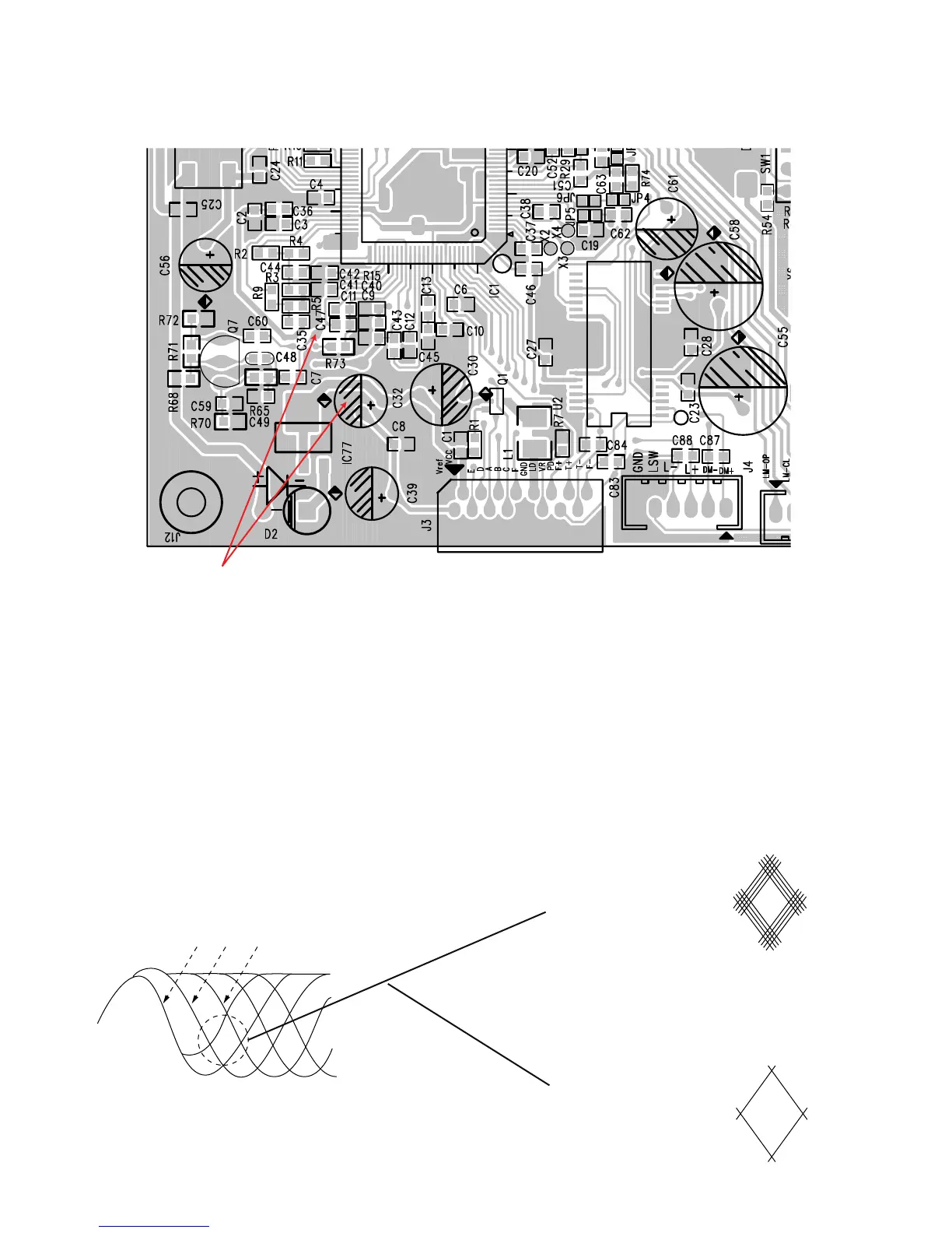
NAD - C 545BEE PCB TESTING POINTS DIAGRAM
TESTING PROCEDURE
(1) Load the test disc (Sony Test CD YEDS-7) and set the unit into PLAY mode.
(2) Connect the scope to C7 (Pin 81 of IC1) and DGND (C32).
Scope setting: Coupling : AC.
Vertical sensitivity : 0.2 V/ div.
Horizontal time base : 0.5 μS/div.
(3) Observe the waveform is 1.5V p-p +/-5% and the eye pattern is at its best shape (see FIG. 1).
FIG. 1 (a) FIG. 1 (b) Poor eye pattern
FIG. 1 (C) Good eye pattern
3T
4T
5T – 11T