Analog I/O Unit
FP0
4-4
Matsushita Automation Controls
4.1 Parts and Terminology
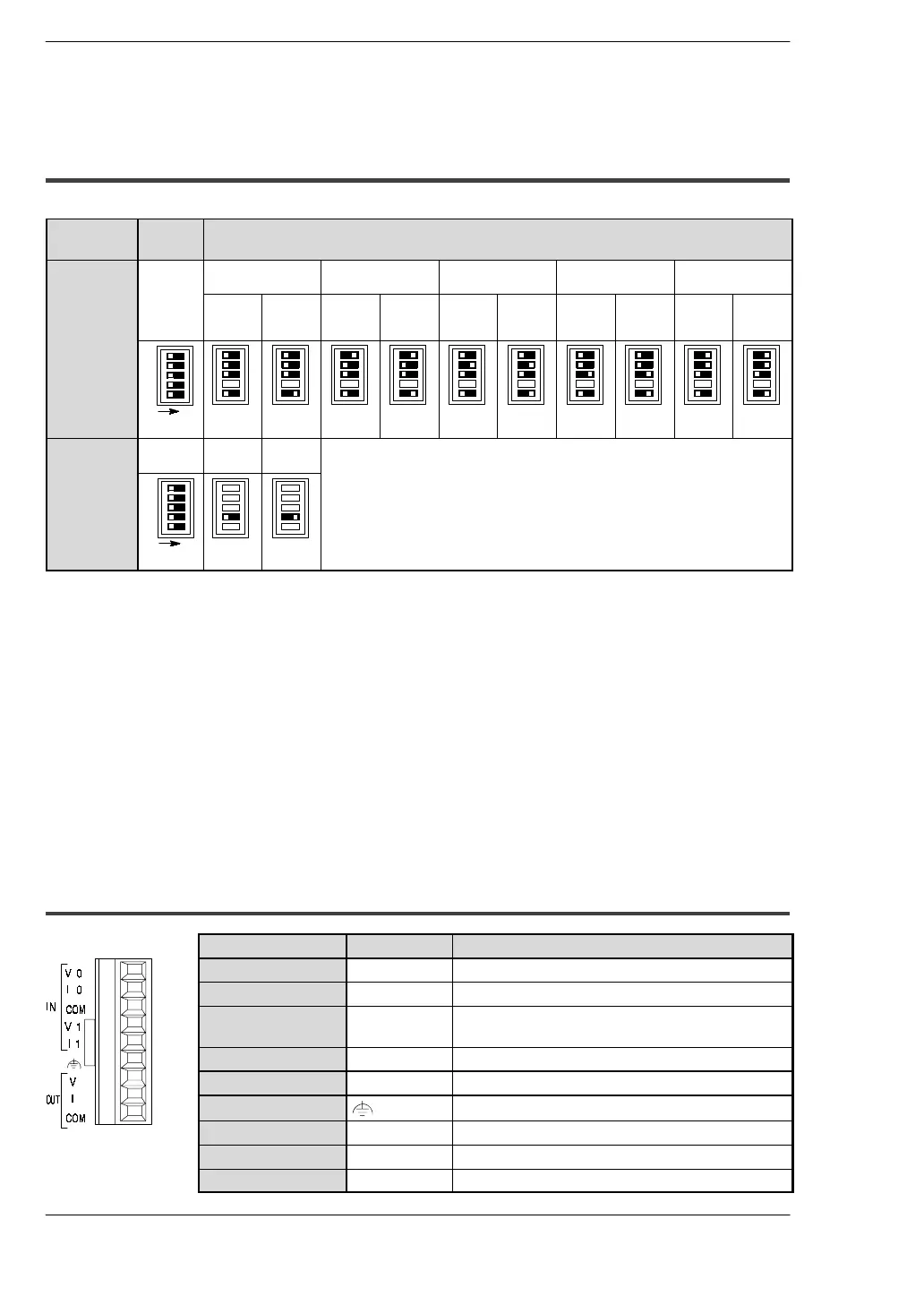
4.1.1 Analog Mode Switch Setting
Analog mode switch
Mode
Switch
number
Range
Analog
0to5V
0 to 20mA
-10 to +10V
K type thermocouple
(
*
Note 3)
J type thermocouple
(
*
Note 3)
T type thermocouple
(
*
Note 3)
range
switching
1to3,5
No averag-
ing
(
*
Note 1)
With aver-
aging
(
*
Note 2)
No averag-
ing
(
*
Note 1)
With aver-
aging
(
*
Note 2)
Tempera-
ture of
terminal to
1000
q
C
- 100
q
Cto
tempera-
ture of
terminal
Tempera-
ture of
terminal to
750
q
C
- 100
q
Cto
tempera-
ture of
terminal
Tempera-
ture of
terminal to
350
q
C
- 100
q
Cto
tempera-
ture of
terminal
1
2
3
ON
5
Analog
4
0to
20mA
-10 to
+10V
range
switching
ON
4
.
Notes
D
(
*
1): No averaging: Conversion data is set for the specified input
contact point area for each A/D conversion, on each channel.
D
(
*
2): W ith averaging: On each channel, for each A/D conversion,
the maximum and minimum values from the data of the
last ten times are excluded, and the data from the other
eight times is averaged, and the result set. (
*
section 4.7.1)
D
(
*
3): If a thermocouple setting is used, averaging is carried out,
regardless of the switch settings. (
*
section 4.7.2)
4.1.2 Analog I/O Terminal
Pin number Name Description
1
IN/V 0 Analog input (channel 0), voltage input
2
IN/I 0 Analog input (channel 0), current input
3
IN/COM Analog input (channel 0 and 1), analog input
common
4
IN/V 1 Analog input (channel 1), voltage input
5
IN/I 1 Analog input (channel 1), current input
6
Ground for analog cable
7
OUT/V Voltage output
8
OUT/I Current output
9
OUT/COM Analog output common

 Loading...