21
IOM
W415-2288 / 08.29.2019
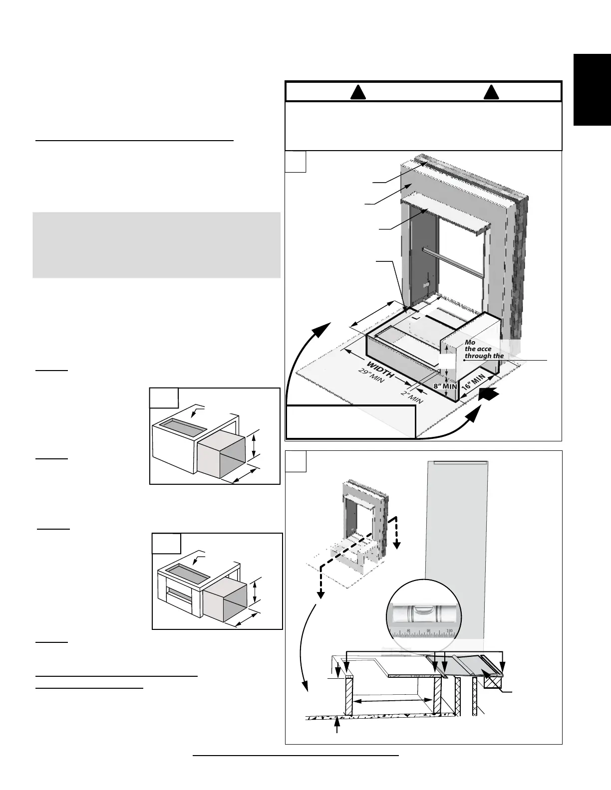
4.5 UNIT SUPPORT
H68.3.5
Wall Sleeve
Inside Wall
Outside Wall
29” MIN
2” MIN
WIDTH
Support
Platform
** MIN Support
Platform Depth
LEVEL
16” MIN
More than 18” will obstruct
the access to the unit
through the side panel.
8” MIN
Return Air
MIN 8”x16”
18”
MAX
** Minimum platform depth
must allow installation of
return air duct with minimum
inside cross section of 8" x 16".
Return Air Opening
24 1/8” x 8 1/4”
DO NOT OPERATE THE FURNACE FOR PROLONGED
PERIODS OF TIME WITHOUT AN AIR FILTER. A ALWAYS
WEAR SAFETY GLASSES WHEN WORKING WITH
TOOLS! OVER-TIGHTENING THE SCREWS MAY STRIP
THE RETAINING HOLES. READ ALL OF THE ASSEMBLY
INSTRUCTIONS STEPS BEFORE PROCEEDING.
CAUTION
! !
The wall sleeve is not intended as the sole support for
the unit. Therefore, additional support must be provided
by a rigid structure that bears the weight of the unit and
provides an interface for “return air” ducting.
In certain jurisdiction, combustible material is not
allowed to be exposed to return air. For those
municipalities, a support structure can be constructed
using either OPTION 2 or OPTION 3 concepts as per
the material availability.
a. Carefully measure the unit and choose a strong
building material for the support structure.
b. The unit should be additionally supported for
leveling purposes.
• First, the supporting platform must be built, see
(FIG. 15). It can be constructed of plywood and
framing lumber. FIG. 16 is showing alignment of the
platform top with the base panel of the wall sleeve.
Before building support structure,
consider the following:
Support Structure Construction OPTIONS:
OPTION 1
(As per fi gure 15, 16):
15
B
B
B
Wall Sleeve
Wall Sleeve
Base Panel
Platform Top
B
B
These surfaces should be level
16” MIN
8” MIN
16
• Minimum height of platform = 8”
• Recommended platform width = 29”
• **Recommended platform depth = to allow
installation of return air duct with minimum inside
cross section of 8” x 16”. Refer to FIG. 15 and 16.
OPTION 2:
Step 1: Construct a three sided box or a two sided frame
to suf ciently support Condo Pack weight (Fig 16A).
An optional rectangular
plywood with 9” x 25”
opening can be mounted
on this structure for
additional support.
Step 2: install a metal
return ducting with 24 1/8”
x 8 1/4” connection to
the unit with minimum 8”
height.
8” MIN
16” MIN
8” MIN
16” MIN
Optional plywood board with
9”x25” opening.
Optional plywood board with
9”x25” opening.
16B
8” MIN
16” MIN
8” MIN
16” MIN
Optional plywood board with
9”x25” opening.
Optional plywood board with
9”x25” opening.
16A
OPTION 3:
Step 1: Construct a three sided or two sided wooden
frame to suf ciently
support Condo Pack
weight (Fig 16B).
An optional rectangular
plywood with 9” x 25”
opening can be mounted
on this structure for an
additional support.
Step 2: install a metal return ducting with 24 1/8” x
8 1/4” connection to the unit with minimum 8” height.