44
IOM
IOM
W415-2288 / 08.29.2019
6.2 SEQUENCES OF OPERATION
6.2.1 Heating Cycle
1. When thermostat switch is set to heat, the terminals R&W get connected which will energize the
indoor blower and all the relays for the heating elements immediately.
2. Relay 1, once energized, turns the rst Heating element ON with up to 1 second delay. At the
same time Relay 2 powers the rest of the heating elements with delay range from 1 to 8 seconds
(applicable to 7.5 kW, 10kW, and 15 kW).
3. When the room thermostat is satised, terminal R and W connection opens and de-energizes all the
relays, blower and heating elements immediately.
6.2.2 Cooling Cycle
6.2.3 Continuous Fan Cycle
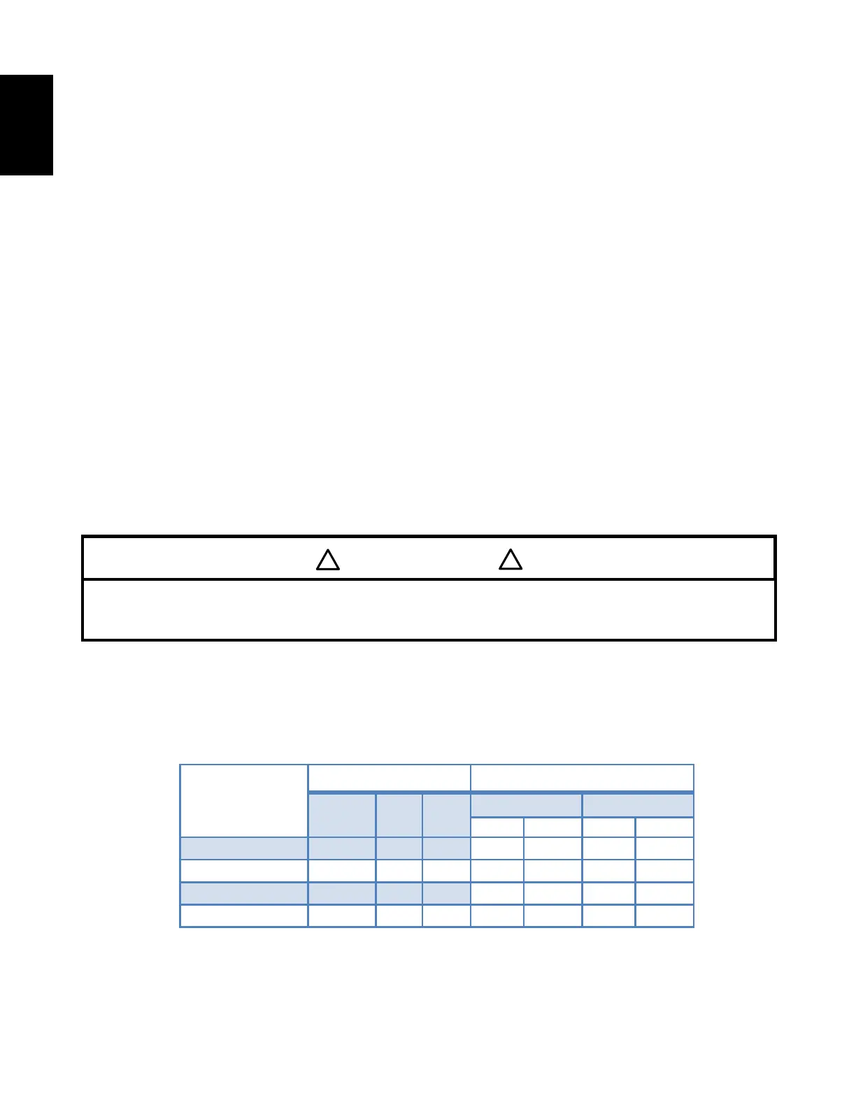
6.2.4 Performance Specication
1. Room thermostat calls for cooling connecting R to Y terminals.
2. The compressor and condenser fan start immediately on a call for cooling. Air circulating fan also
starts immediately with cooling operation.
3. When the room thermostat is satised, terminal Y on the module is de-energized.
4. The compressor and condenser fan stop immediately when the thermostat is satised.
1. When thermostat switch is set to FAN, the terminals R & G get connected which will energize the
indoor blower to circulate the indoor air.
2. The indoor blower will continue to run until the thermostat setting is changed to different
operational mode.
Model No.
COOLING HEATING
BTU/h EER CFM
TABLE 5.
CONTINUOUS FAN SPEED TAP SHOULD NOT BE CHANGED FROM FACTORY SETTING.
DO NOT USE COMMON SPEED TAP FOR MULTIPLE FUNCTIONS; IT CAN CAUSE UNIT TO
MALFUNCTION.
IMPORTANT
!
!