- 13 -
MICROSOFT WORD 2002 89-22091 / VERSION 1 / 13.03 2007
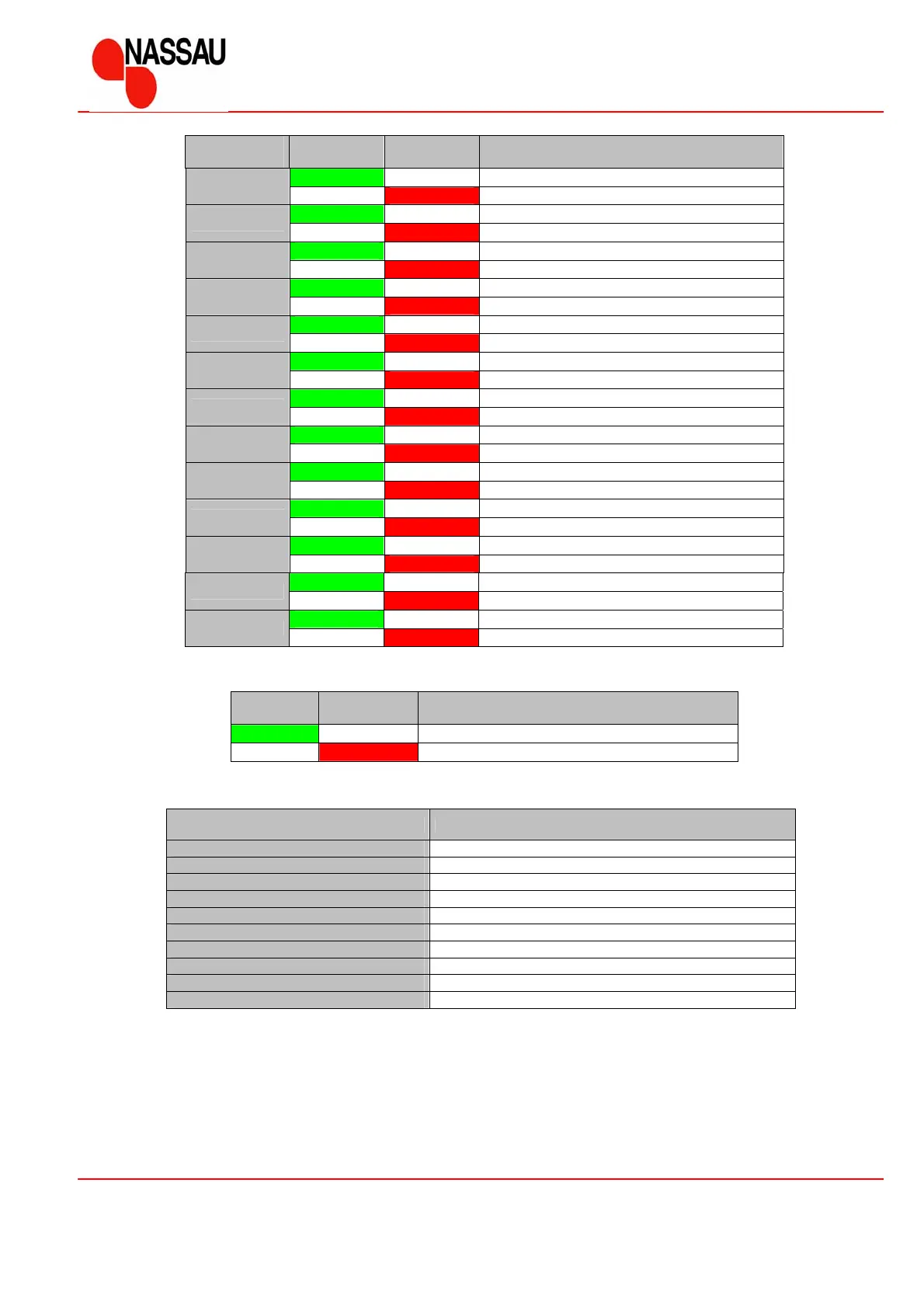
Functional description for control unit ED520
The indicator lamps will indicate the actual mode of the operation, if SW1 or SW2 are not activated.
LD1
Green
LD2
Red
Description
Normal operation
Error – the display will indicate the type of error
The display will indicate the error code according to the below table, if faults are detected
Error code Description
0 Run-in
1 Stop circuit is activated
2 Safety edge is defect
3 Photocell is defective
4 Not in use
5 Memory error (program or data)
6 Unexpected function of contactors
7 Speed control encoder error
8 Wear error (speed control encoder )
9 Anti crushing error (speed control encoder )
Indication
number
LD1
Green
LD2
Red
Description
E-Stop [ S4 ] NC – Stop circuit ok
1
E-Stop [ S4 ] NC – Stop circuit interrupted
D-Stop NO – Activated
2
D-Stop NO – Not activated
Up [ S5 ] NO – Activated
3
Up [ S5 ] NO – Not activated
Down [ S6 ] NO – Activated
4
Down [ S6 ] NO – Not activated
Pull switch [ S10 ] NO – Activated
5
Pull switch [ S10 ] NO – Not activated
Extra [ S13 ] NO – Activated
6
Extra [ S13 ] NO – Not activated
Top limit – Door at top position
7
Top limit – Door not at top position
Bottom limit – Door at bottom position
8
Bottom limit – Door not at bottom position
Safety edge [ S7 ] NC – Not activated
9
Safety edge [ S7 ] NC – Activated
Photocell [ S12 ] NC – Not activated
10
Photocell [ S12 ] NC - Activated
½ - up [ S14 ] NO – Activated
11
½ - up [ S14 ] NO – Not activated
Gear ON/OFF [ S2 ]– Not activated
12
Gear ON/OFF [ S2 ]– Activated
Anti-crushing device – Not activated
13
Anti-crushing device – Activated