- 19 -
MICROSOFT WORD 2002 89-22091 / VERSION 1 / 13.03 2007
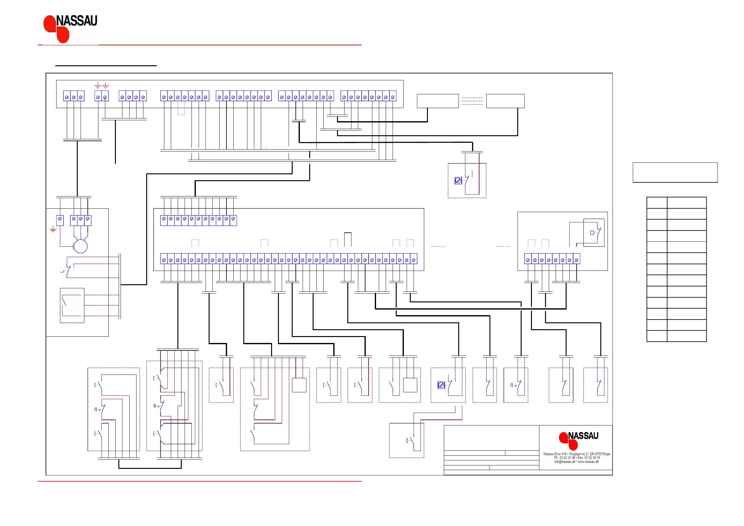
Functional description for control unit ED520
3
2
1
5
4
8
7
6
11
10
9
Brown
12
White-black
Black
Blue
Red
Pink
Grey
White-brown
Purple
Red-blue
Red-brown
White-blue
Colour of the conductor of
the control cables 0.5mm²
No.: Colour:
VU
7
W L1 L3L2 N 1 32 4 5
8
76 8 9 1110 12 13 1514 16 17
LIYY -
1918
12x0.5mm²
20
M
22 2423 25 26 2827 29 30 3114A
ED400/500 mainboard
4
3
2
LIY Y - 6x0.5mm²
5
4
1 2 3 54 6 7 98 10 11
12 13 14 15 16 1817 19 20 21 22 23 24 2625 27 28 3029 31 32 3433 35 36 3837 39 40 4241 43 44 4645 47 48
S13
S2
S5
S6
2
1
S4
( IF NO PHOTOCELLS - TERMINAL 24 AND 26 MUST BE CONNECTED )
S35 OPEN DOOR
S34 STOP DOOR
S36 CLOSE DOOR
3
S7
S13
2
1
3
2
1
3
2
OPEN DOOR - OUTSIDE
AUTO/MAN.
S15
6
5x1.5mm²
HO5RR-F
1
4
3
2
S10
2
1
Description:
Size:
Drawing no.: Version:
Drawn:
Sheet of
Released:
By :
By :
Name of project:
File:
BJO
BJO
88-20024 1.0
ED520 Wirediagram
A3 1 1
ED520
HO5RR-F
4x1.5mm²
LIYY -
LIYY -
LIYY -
LIYY -
LIYY -
4x0.5mm²
LIYY - 6x0.5mm²
Gearmotor
Preinstalled jumper
3
2
1
S12S11
4x0.5mm²
2x0.5mm²
2x0.5mm²
2x0.5mm²
JB400
DW400
S30
5
4
3
2
1
8
7
6
S31
Radio remote control
Pushbutton box -
S32
2x0.5mm²
2x0.5mm²
LIYY -
LIYY -
2x0.5mm²
4
3
2
1
1
2
2
1
1
3
4
2
1
2
2
1
10
9
8
7
6
5
4
3
11
1
1
S1
24VDC
2
1
1
2
2
1
Radar/ Detector
1
1
2
2
2
1
1
1
1
2
2
2
6
5
4
3
2
1
Nov 07, 2006
Nov 07, 2006
Preinstalled jumpers
S2 GEAR ON/OFF
1
1
2
2
1
6
5
8
7
4
3
2
S5 OPEN DOOR
S4 STOP
S3 LOCK/WIRE
S13 AUTO/MAN. - EXTRA
S1 2 PHOTOCELL RECEIV ER
S11 PHOTOCELL TRANSMITTER
S10 PULL SWITCH
S9
S8 SPEED CONTROL ENCODER
S7 DW-SWITCH
S6 CLOSE DOOR
S17 DOOR SW.
S16 SPRING
S15 STOP
S14 ½ -UP
S16
LIY Y - 2x0.5mm²
S18
5
4
Place jumper at terminals 38 and 39, if controller in autoclose mode
S17S19
S32 RADIO - CLOSE DOOR
S31 RADIO - STOP DOOR
S30 RADIO - OPEN DOOR
and no AUTO/MAN. sw itch installed.
+24 VD C
S8
GND
Speed control encoder
S1 9 PULL - OPEN DOOR
S1 8 PULL - OPEN DOOR
LIYY - 2x0.5mm²
S33 RADAR - OPEN DOOR
S3
8
9
7
6
LIYY - 2x0.5mm²
LIYY - 8x0.5mm²
4
3
2
1
-
+
U
4
2
V
LIYY - 6x0.5mm²
2
2
1
W
4
3
2
1
RADAR ON/OFF
3
1
6
5
4
1
6
5
4
3
2
1
2
11
10
2
1
4
3
1
2 3 4
S35
S34
S36
5
Pushbutton box -
S14
5
6
2x0.12mm²
3x400 + Pe
LIN E
1
2
3
4
5
6
6
1
5
InsideOutside
3x0.12mm²
S33
24VDC
+
-
Photocell receiverPhotocell transmitter
14 ED520 Connections diagram