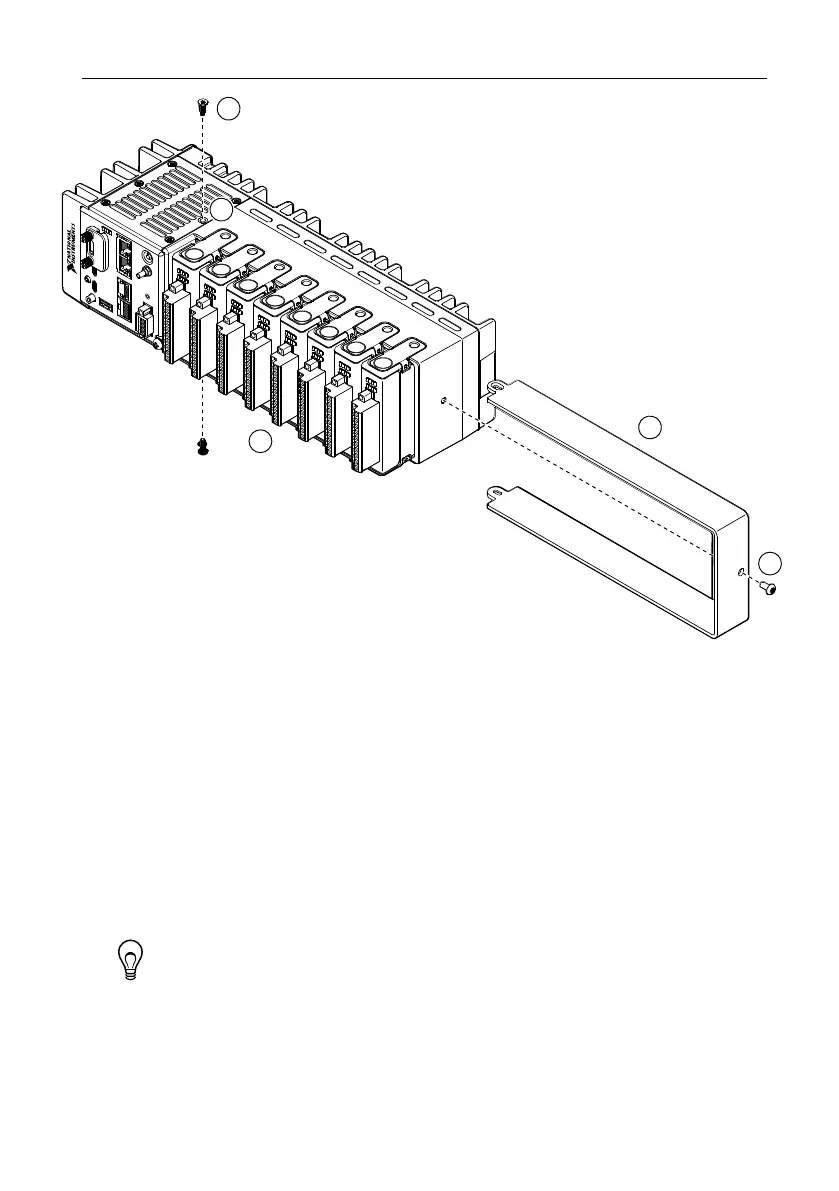
Figure 8. 8-slot cRIO-904x Module Immobilization Accessory Installation
1. Ensure that all the C Series modules are installed in the cRIO-904x and the latches are
locked in place.
2. Remove the center right panel screw from the top and bottom of the cRIO-904x using the
Torx T10 driver.
3. Slide the bracket into place, aligning the three clearance screw holes.
4. Install the M4 x 0.7 button-head screw in the right end of the cRIO-904x using the
appropriate Torx T20 driver. Tighten the screw to a maximum torque of 1.3 N · m
(11.5 lb · in.).
5. Install the two M3 x 0.5 flat-head screws from the accessory kit in the top and bottom of
the cRIO-904x using the appropriate Torx T10 driver. Tighten the screws to a maximum
torque of 1.3 N · m (11.5 lb · in.).
Tip NI recommends using a liquid thread locker for all fasteners if the system
is expected to experience vibration for an extended amount or time.
Module Immobilization Accessory Dimensions
The following figure shows the Module Immobilization accessory dimensions for the
cRIO-904x.
24 | ni.com | cRIO-904x User Manual
 Loading...