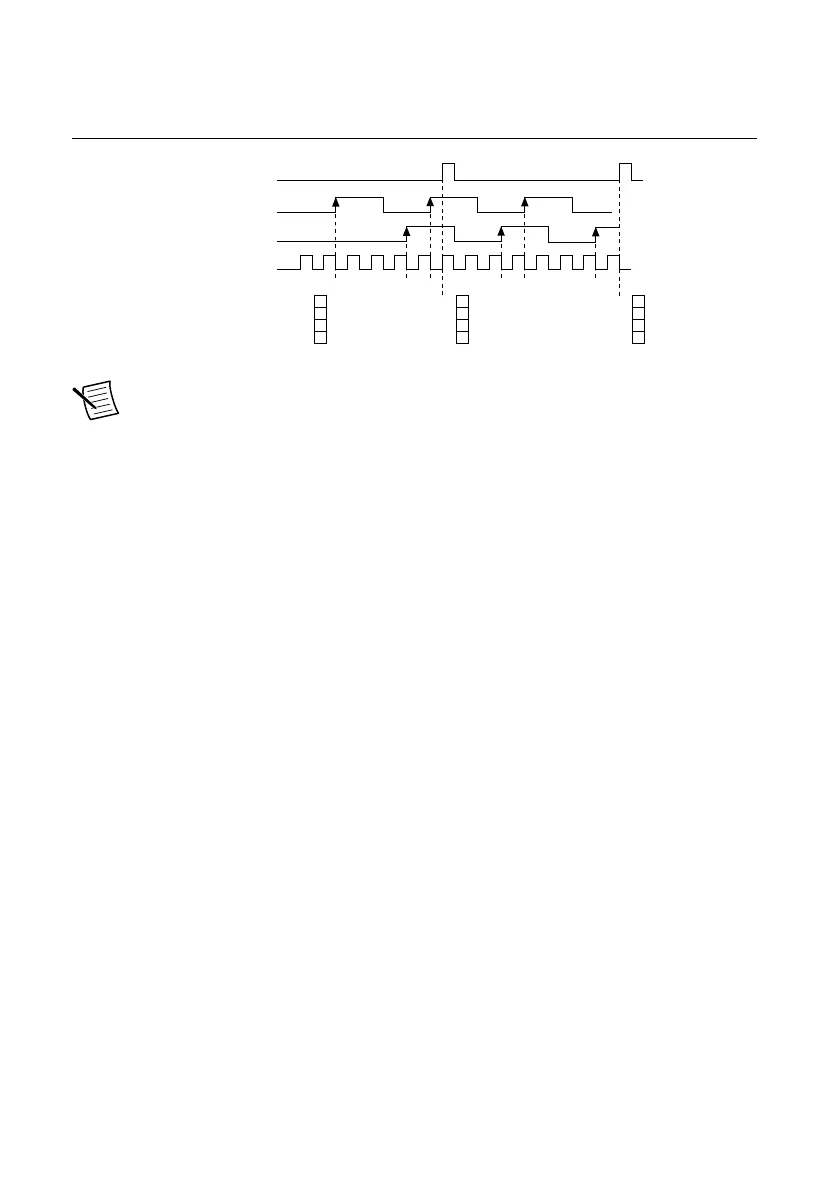
The figure below shows an example of a sample clocked buffered two-signal separation
measurement.
Figure 73. Sample Clocked Buffered Two-Signal Separation Measurement
SOURCE
Counter Value
Buffer
AUX
GATE
1 2 3 1 2 3 1 2 3
3 3
3
Sample
Clock
Note If an active edge on the Gate and an active edge on the Aux does not occur
between sample clocks, an overrun error occurs.
For information about connecting counter signals, refer to the Default Counter/Timer Routing
section.
Counter Output Applications
The following sections list the various counter output applications available on the cRIO
controller:
• Simple Pulse Generation
• Pulse Train Generation
• Frequency Generation
• Frequency Division
• Pulse Generation for ETS
Simple Pulse Generation
Refer to the following sections for more information about the cRIO controller simple pulse
generation options:
• Single Pulse Generation
• Single Pulse Generation with Start Trigger
Single Pulse Generation
The counter can output a single pulse. The pulse appears on the Counter n Internal Output
signal of the counter.
You can specify a delay from when the counter is armed to the beginning of the pulse. The
delay is measured in terms of a number of active edges of the Source input.
cRIO-904x User Manual | © National Instruments | 97
 Loading...