Appendix A Device-Specific Information
M Series User Manual A-22 ni.com
Digital I/O and Timing I/O
You can access digital I/O and timing I/O signals on the BNC connectors
labeled PFI <0..7>/P1.<0..7>. Figure A-10 shows the DIO/TIO circuitry on
the USB-6221 BNC.
Figure A-10. Digital I/O and Timing I/O Circuitry
Refer to the Connecting Digital I/O Signals section of Chapter 6, Digital
I/O, and the Connecting PFI Input Signals section of Chapter 8, PFI, for
more information.
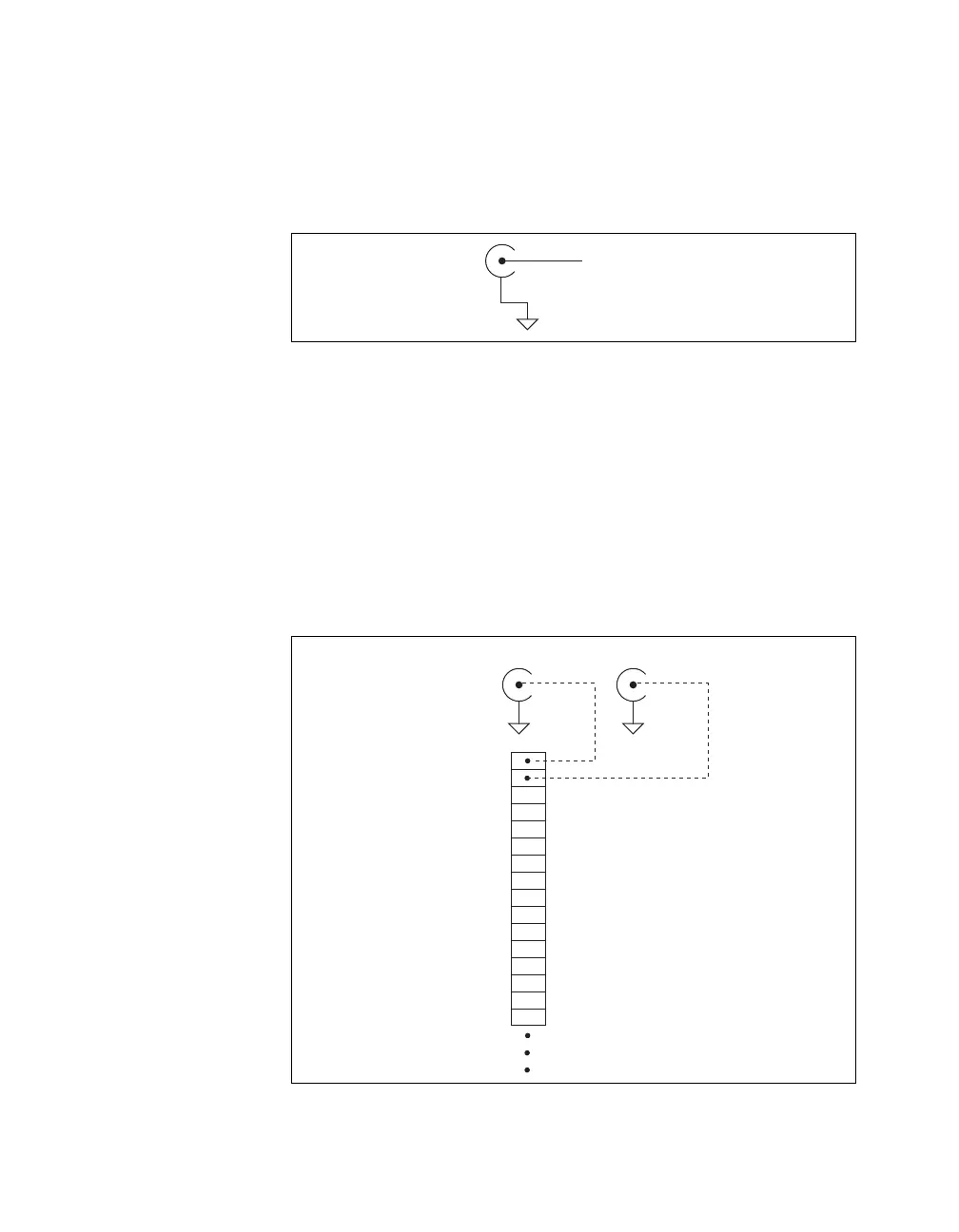
USER 1 and USER 2
The USER 1 and USER 2 BNC connectors allow you to use a BNC
connector for a digital or timing I/O signal of your choice. The USER 1 and
USER 2 BNC connectors are routed (internal to the USB-6221 BNC) to the
USER 1 and USER 2 screw terminals, as shown in Figure A-11.
Figure A-11. USER <1..2> BNC Connections
PFI
x
/P1.
D GND
USER 2 BNC
D GND
USER 1
P0.6
P0.5
P0.4
D GND
P0.3
P0.2
P0.1
P0.0
D GND
+5 V
D GND
USER 2
PFI 8/P2.0
P0.7
D GND
Internal Connection
USER 1 BNC
D GND
Screw
Terminal
Block

 Loading...