Appendix B Timing Diagrams
M Series User Manual B-20 ni.com
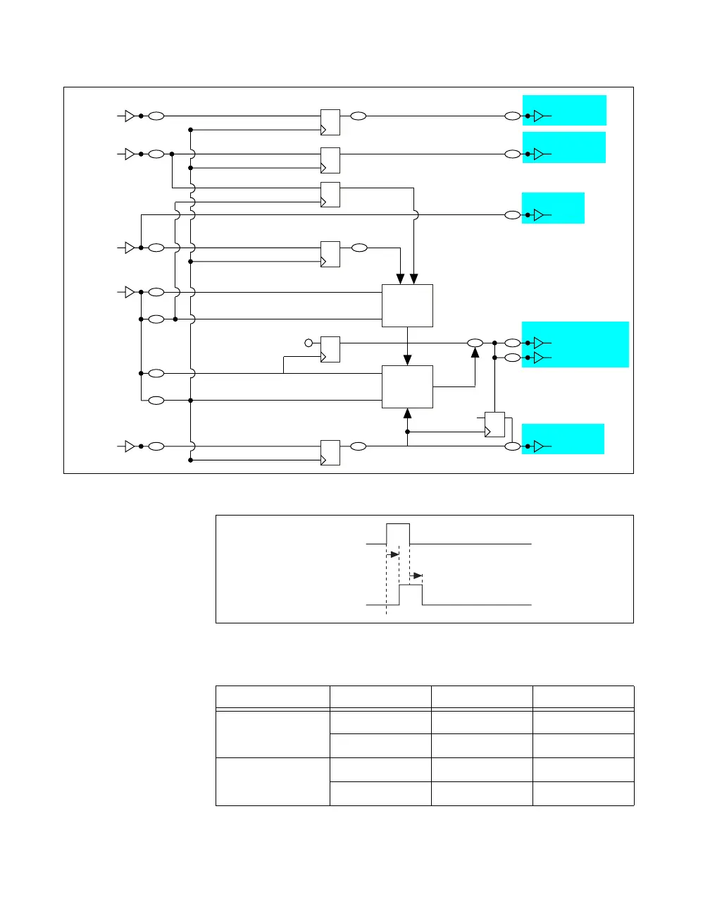
Figure B-20. Output Timing and the Analog Input Timing Engine
Figure B-21. Output Timing Diagram
Table B-11. Output Timing
Edge Line Min (ns) Max (ns)
Rising Edge PFI 7.2 25.7
RTSI 5.6 14.0
Falling Edge PFI 7.5 25.9
RTSI 6.0 13.9
Start
Terminal
Selected Reference Trigger Reference Trigger
Terminal
Terminal
Selected Sample Clock
Terminal
Terminal
Terminal
Selected Start
RTSI
Terminal
Terminal
Terminal
Selected Pause Trigger
SI
Counter
Block
SI2
Counter
Block
SI_TC
Sample Clock Timebase
Sync Sample Clock Timebase
Convert Clock Timebase
Sync Convert Clock Timebase
SI Start
Pause Trigger
p_AI_Convert
Start
1
POUT
POUT
POUT
POUT
POUT
SI2_TC
POUT
Terminal
t
39
t
40

 Loading...