PXIe-4466/4467 Calibration Procedure
© National Instruments Corporation 23
7. Measure the output voltage with the DMM.
8. Stop and clear the task.
9. Compare the result with the limits in Table 11.
AO Differential Gain Accuracy Verification
Test Limits
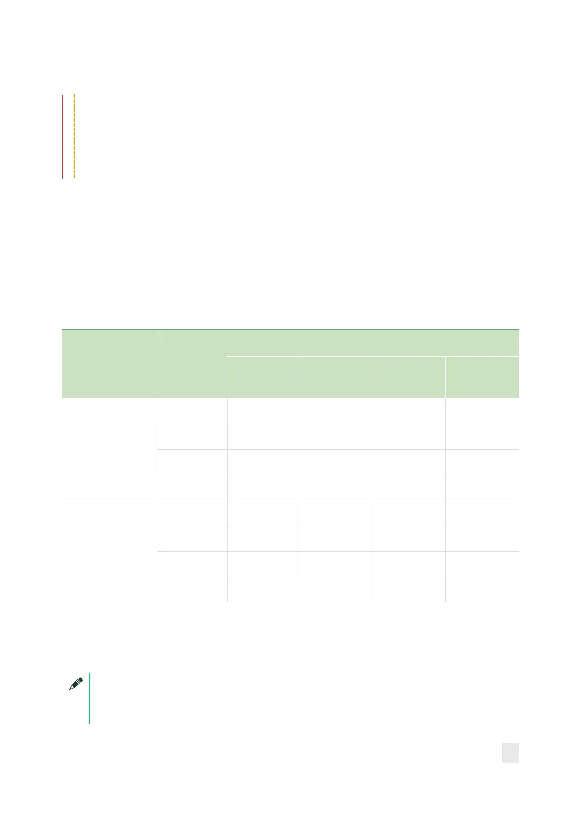
Table 15: AO Differential Gain Verification Limits
Output Terminal
Configuration
AO
Attenuation
(dB)
As-Found Test Limit As-Left Test Limit
Lower Limit
(V
rms
)
Upper Limit
(V
rms
)
Lower Limit
(V
rms
)
Upper Limit
(V
rms
)
Differential
0 6.27828 6.32180 6.29710 6.30290
10 1.99310 2.00692 1.99908 2.0092
20 0.62783 0.63218 0.62971 0.63029
30 0.19931 0.20069 0.19991 0.20009
Pseudodifferential
0 6.27828 6.32180 6.28623 6.31380
10 1.99310 2.00692 1.99563 2.00438
20 0.62783 0.63218 0.62862 0.63138
30 0.19931 0.20069 0.19956 0.20044
Initial Test Connection
Note
Initial test connection is same as AO Differential Offset, as shown in
Figure 3.
 Loading...


