Chapter 3 Configuring Your SCXI Hardware and Software
© National Instruments Corporation 3-5 Getting Started with SCXI
only one location along the entire signal path to prevent saturation of the amplifier and
reduce common-mode noise.
If all of the sources are floating, you can configure jumper W1 to
connect a 100 kΩ resistor to the negative input of the amplifier to
prevent saturation. This reduces the input impedance, however, and
usually increases settling time and common-mode noise. Also, if W1
is connected to the 100 kΩ resistor and any of the sources are
ground-referenced or have high leakage to ground, a ground loop can
result, causing DC offsets or noise.
2. Configure the filtering.
The SCXI-1100 has two lowpass, one-pole resistance-capacitor (RC)
filters, with bandwidths of 10 kHz and 4 Hz, positioned after the
amplifier. You select filtering by setting a single jumper to one of three
positions—W2, W3, or W4. Table 3-2 shows the SCXI-1100 filtering
jumper configuration.
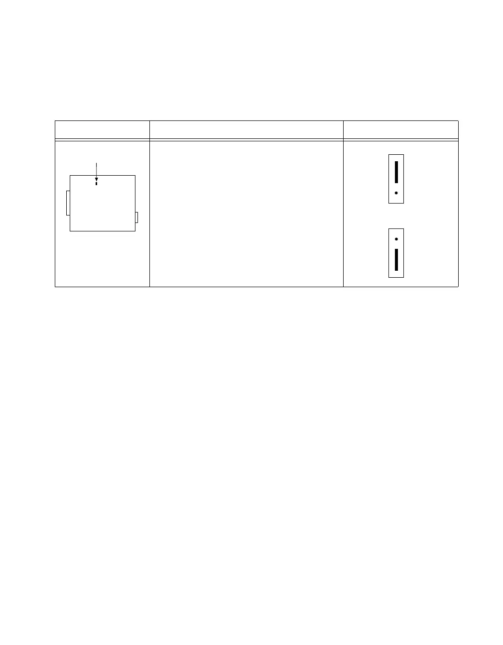
Table 3-1. SCXI-1100 Input Signal Referencing Jumper Configurations
Jumper Description Configuration
1-2 Position—Ground-referenced source
position (factory-default position).
2-3 Position—Floating (nonreferenced)
source position (connects an internal 100 kΩ
resistor from CH- to ground). Read the text in
this section for the implications of using this
position.
W1
1
2
3
1
2
3
 Loading...