Brainz BRM3 Brain Monitor Reference Manual | 19
Setting the system date and time
When you first receive your BRM3 Brain Monitor you should set the system date and time appropriately, for your time
zone. After that, you should only have to change the time to take account of daylight savings changes.
To set the system date and time:
1. On the
Main Menu screen, touch System Setup to display the System Setup screen.
2. Touch
Set Date and Time to display the Set Date and Time screen.
3. To change the year or month, touch one of the two arrows on either side of the year/month, at the top of the
calendar, as appropriate.
4. To change the date, touch the correct date on the calendar.
5. To change the time, touch the arrows next to the
Hour, Minute and Second fields, as appropriate.
6. Touch
Apply to set the current system date and time to the values you entered.
Checking for normal operation
The BRM3 Brain Monitor is supplied with a test plug, attached to the DAU. The test plug can be used to terminate each EEG
channel for test purposes. This procedure constitutes a functional test of the EEG channels and sensor monitoring circuitry.
This check should be performed when the BRM3 Brain Monitor is first assembled, if incorrect operation is suspected, and as
part of the annual maintenance check.
If personal accounts have not been set up on your BRM3 Brain Monitor, use the user name “NICU”, with password “NICU”.
Do not insert the test plug into the DAU before completing patient details and exiting the
Patient Details screen, as this may
cause a delay in starting the test assessment.
To check the BRM3 Brain Monitor for normal operation:
1. On the
Main Menu screen, touch Assess Patient to display the Patient Details screen.
2. Enter a fictitious Patient ID, Patient Name, and Clinician’s Initials. Touch
OK to display the Signal Status screen.
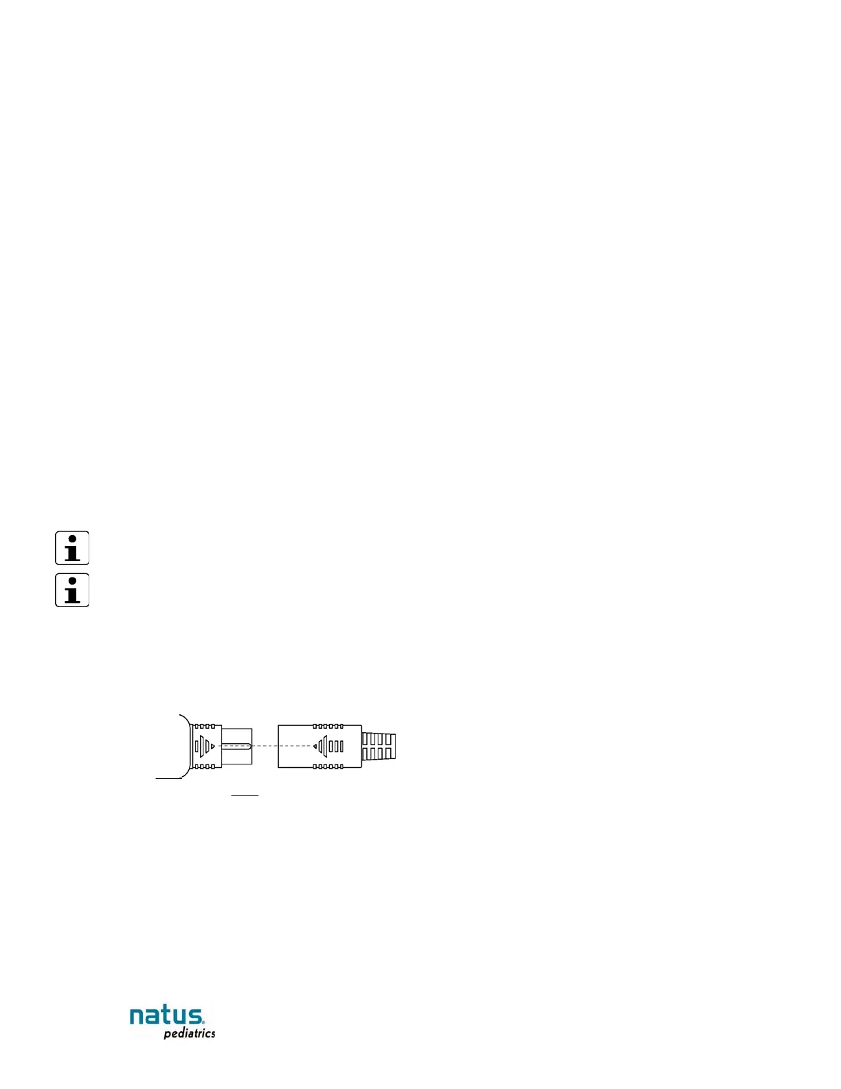
3. Connect the test plug to the DAU, in place of the Neonatal Sensor Set or Sensor Adaptor Set. Make sure the arrows are
aligned to prevent damage to the connectors.
Figure 9: Plug arrows aligned
Expected result: The Sensor Signal Left and Right graphs should display low level “flat”
patterns, and the sensor impedance numbers and sensor indicators should read as shown in the following table:
 Loading...