Xltek EMU128 Headbox User & Service Manual
19
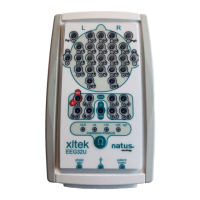
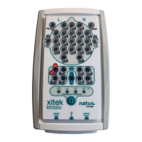
Circuit Board Assemblies Inside the Headbox:
(Block Diagram)
A. Analog Back Plane Board (Qty. 1)
•
A 4 MHz crystal oscillator supplies the reference clock to all the Digital Boards.
•
A 129
th
channel, non-digitized Reference amplifier allows the user to quickly plug
in any one of the 128 acquisition channels and evaluate for suitability as a
reference. The amplified reference signal is routed to all four Analog boards.
B. Digital Motherboard PCB (Qty. 1)
•
Incorporates the I/O connector for the cable to the computer.
•
Combines the time-division-multiplexed data frames from the four 32-channel
groups and transmits the data on differential pairs to the computer.
•
Contains differential driver and receiver for the asynchronous command channel
(19.53Kbaud).
C. Relay Matrix Board (Qty.4)
(Older versions of EMU128 use Connector Board, P/N 101313, having no active
circuitry, only connections from the input connectors to the Analog Boards.)
•
Patient connections are made through these boards through 37-pin D connectors
protruding through the front panel.
•
Sixty-four relays per board allow connection of a stimulus current to one pair of
electrodes at a time from another front-panel jack.
•
EEG signals pass to the Analog PCB for amplification and conditioning.
NOTE The channel numbering on this and other boards is not the same as the EEG
channel numbering.
D. Analog Board (Qty. 4)
•
Handles amplification and DC removal for 32 channels.
•
Amplifiers are designed to handle signals far in excess of even abnormally high
EEG, while also providing exceptional sensitivity and resolution.
•
Two time constants are available in the DC removal. A normal time constant and
a short time constant for accelerated recovery during Trace Restore.
E. Digital Board (Qty. 4)
•
Analog-to-Digital converters digitize the amplified EEG signals. Signals are
periodically sampled and converted to a binary number.
•
The micro controller transmits the digitized signals to the Analog Back Plane
Board that in turn sends them to the computer.
•
Contains non-volatile storage for calibration values.
•
During factory calibration, the NeuroWorks computer calculates and transmits the
channels gains to each digital board. Whenever a study starts, the computer
uses these stored values to scale the digitized signals, channel by channel.
•
The Digital Board for channels 1-32 is connected to the Patient Event front-panel
connector. It detects an Event Switch closure and transmits it to the computer.
F. Breakout Box:
(Schematic diagram is SD-102697 Rev A.)
This unit is completely passive.
•
Patient leads connect to the Breakout Box.
•
Four cables connect the Breakout Box to the computer. The connecting cable
transposes left and right pins. For example, pin 2 at the Breakout Box connects
to pin 18 at the Headbox.
 Loading...