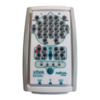
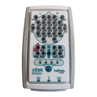
User & Service Manual Xltek EMU 128 Headbox
22
R33/C11/D1 delays enabling the outputs until the Digital PCB clears any random setting
at power up. No more than two relays are supposed to be energized at a time.
Analog Board
(Schematic diagram SD-101315 Rev D3)
Sheet 1 shows the connectors. P2-P5 bring in the EEG signals from the Relay Matrix
Board. P1 conveys the amplified signals to the Digital Board. J101 connects to the
Analog Back Plane and brings in the amplified Reference signal. Sheet 2 shows the shift
registers that control analog switches. The shift registers give the Digital PCB control of
modes of operation and allow the Digital PCB to short circuit individual channel inputs
(sheets 5-8). The computer commands this when a channel is not in use or during
impedance checking.
U1205 controls the modes of operation as follows:
•
Signal SREC controls analog switches in each channel whose closure accelerates
the time constant of the DC removal circuitry (as previously described for the Analog
Back Plane).
•
Signals REFON1, REFON2, XREFON1 and XREFON2 control reference selection
(sheets 3, 4). One of these may be on (logic 1), or none (if the user sets the
reference to Common).
CALON sets a path (sheet 3) for the Channel Test signal from the Digital PCB to do an
end-to-end verification of amplifier operation.
IMPON makes the path for VSIG to supply a current to channel inputs for impedance
checking. Impedance checking is not enabled for the EMU128. Sheet 3 shows the
amplifiers for the reference signal and the Channel Test signal (designated VCAL).
Sheets 9 through 40 show circuit diagrams for the 32 amplifier channels. These are all
the same except that Channels 8 and 24 make available the outputs of the second gain
stage for use as a reference. This feature is provided to enable the “linked ears”
(A1+A2/2) reference for the EEG32 and is not used by EMU128 software.
The amplifier works as previously described for the Reference amplifier on the Analog
Back Plane, with these differences:
•
The 50 Meg ohm input resistor is returned to the output of U1302-A for impedance
checking when the assembly is used in an EEG32.
•
The second gain stage output gets applied to the 4.7K input resistor of a third gain
stage configured for an inverting gain of 4.34.
•
The Reference signal is scaled and inverted by U1301-A so that when it is summed
in the third gain stage, it ends up being subtracted from the signal that is being
monitored.
•
The negative input of an inverting stage functions as a summing junction for signals
applied to all resistors tied to this junction.
 Loading...