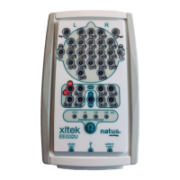
User & Service Manual Xltek EMU 128 Headbox
20
Board-Level Theory
Analog Back Plane
(Schematic diagram SD-102196 Rev B1)
U1 is a dual phase-locked loop chip, of which only the oscillator portion is used. The
frequency is established by quartz crystal Y1. The output from pin 7 is filtered to an
almost pure 4 MHz sine wave by parallel-resonant circuit C1, L1. This suppresses
radiated emissions that would exceed certain regulatory limits. The signal is coupled by
C2 and R1 to the FREF pins on connectors P1-P4, into which are plugged the four
Digital PCBs. D1 and D2 combine the +5V from all four Digital boards. Even if there is a
failure on one of the boards the oscillator is still powered. If the oscillator stops working
the Headbox appears to be dead.
The Reference amplifier on sheet 3 is powered by N5VL and P5VL (-5V and +5V) from
P5. The amplifier output gets fed to the four Analog boards on pin 17, XREFIN2, of
board connectors P5-P8. Signal SREC, P5-18, transmits to analog switch U2 control
input. This closes the circuit from VFBH01 to VFBL01 and shortens the DC removal
time constant during Trace Restore.
The amplifier on sheet 3 uses two gain stages plus an integrator for DC removal. This is
equivalent to AC coupling but achieves a very low cutoff frequency without needing a
large value of capacitance. The Reference signal, REFIN, is applied to non-inverting
amplifier U3-A. Diode D3 protects against Electro-Static Discharge (ESD).
Capacitor C12 prevents interference from powerful stations in the standard AM
broadcast band. The 50 Meg ohm input resistor provides a path for the tiny bias current
of the input stage of the op amp and establishes the input impedance of the amplifier.
The feedback resistors in RN35 yield a gain of 4.05 for this stage. The gain of the
second stage, U4-A, is -(140/15.4)= -9.09. C10 and C11 low pass filter the output with a
corner frequency of approximately 8 KHz. Any DC on the electrode (caused the reaction
of the electrode metal with the patient’s skin) is integrated by U4-B. The opposite polarity
is then applied to the second gain stage through voltage divider R4, R5. The corner
frequency is approximately a tenth of a Hz and is determined by components C3, R4,
R5, R6, R7, RN35(1K), as well as the gain of the second stage. The amplified reference
signal is fed to the four Analog boards as signal XREFIN2. U3-B is not active. You can
tell if the amplifier is working because, with the reference set to External (Edit-
>Settings->Acquisition tab), a signal of any sort on this input should appear on all
channels.
 Loading...