NV10LT/NV7.5LT INSTALLATION MANUAL INSTALLING OPTIONS
VERSION 5.0 2021-03-01 PAGE 2.3.5
Installing the Remote Interface PWB
The NV10LT/NV7.5LT is factory configured with a controller (A4), which provides remote control and
monitoring interfacing on its rear panel. You can install a remote interface PWB (Nautel Part #
NAPI143/01) behind the hinged, front UI panel, which provides a more convenient location to make
remote wiring connections. The remote interface PWB also contains control switches (push-buttons)
and monitoring LEDs, which provide backup control and monitoring for the transmitter in the event of a
failure with the front panel UI or remote AUI. It also provides analog output samples of key parameters
(forward power, reflected power, PA voltage and total current) for monitoring.
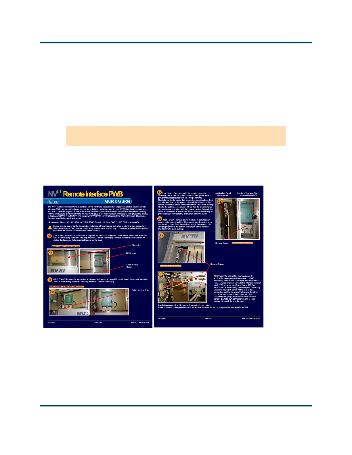
1. Obtain “QG12006* - NVLT Remote Interface PWB Upgrade Quick Guide” (see Figure 2.3.4) that
was provided with the Remote Interface PWB Upgrade Kit and complete its outlined procedure.
Figure 2.3.4: Remote Interface PWB Quick Guide (QG12006*)
2. If you are performing this upgrade in conjunction with the NV10LT/NV7.5LT’s initial installation,
leave the front panel off to allow further installation. If you are performing this upgrade after initial
installation has already been completed, re-install the front panel.
NOTE: Installing this option changes the location of remote control/monitor and interlock connections.
See Section 2.8, “Installing Control/Monitor Wiring” on page 8-1 for more information.
WARNING! ENSURE THAT AC POWER IS NOT BEING APPLIED TO THE
TRANSMITTER DURING THIS PROCEDURE.