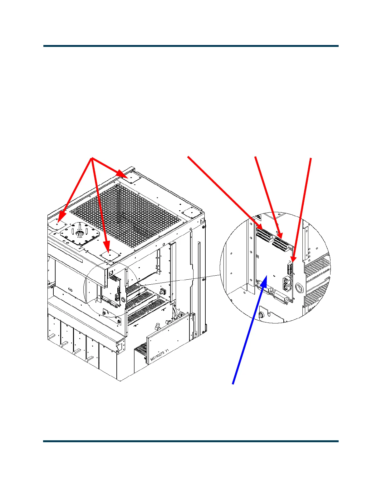
OPTIONAL REMOTE
INTERFACE PWB (A16)
EXTERNAL
INTERLOCK
TB1 (terminals
1 and 2)
FRONT DOOR AND SIDE PANEL
REMOVED FOR CLARITY
** EACH REMOTE CONTROL/MONITOR ENTRY HOLE HAS A REMOVEABLE PLATE WITH A PRE
CUT 1/4-INCH DIA HOLE. USE A CHASSIS PUNCH TOOL (e.g., GREENLEE) TO CREATE DESIRED
HOLE SIZE IN THE PLATE(S). REMOVE EACH PLATE (FOUR M4 SCREWS) BEFORE PUNCHING.
REMOTE CONTROL/
MONITOR ENTRY OPTIONS**
Use front holes (right hole preferred)
for remote interface PWB
connections (including LAN), if used.
Use rear hole for controller
connections (including LAN) if remote
interface PWB is not installed.
REMOVE THE PLATE TO ACCESS A 2.5-INCH HOLE, IF NECESSARY.
CUSTOMER
ALARM/STATUS
TERMINAL BLOCK
TB2 (26 terminals)
CUSTOMER
CONTROL
TERMINAL BLOCK
TB3 (26 terminals)