NV10LT/NV7.5LT INSTALLATION MANUAL COMMISSIONING
VERSION 5.0 2021-03-01 PAGE 2.9.7
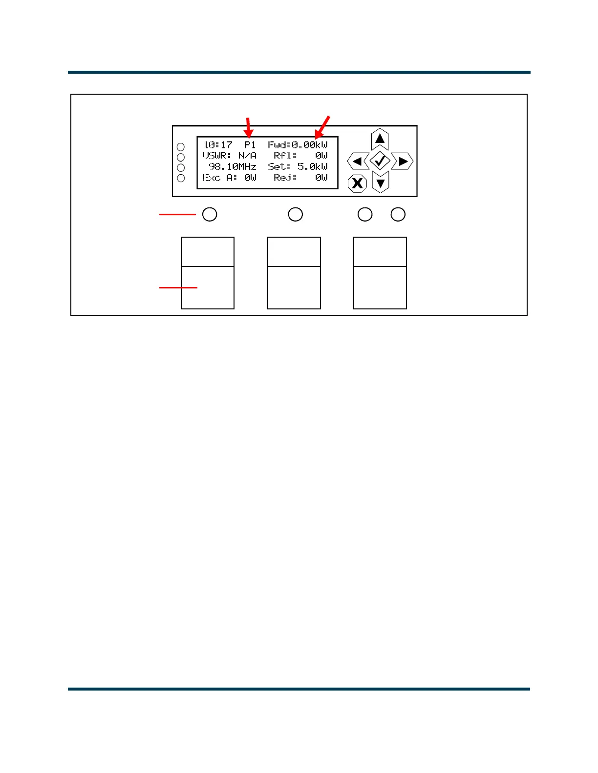
Figure 2.9.5: Front Panel User Interface
5. In local mode (Local LED will be amber, see Figure 2.9.5), enable the NV10LT/NV7.5LT’s RF output
by pressing the RF On switch (see Figure 2.9.5). The RF On status LED should turn amber,
indicating RF power is enabled. The NV10LT/NV7.5LT should be operating at the output power
level set during the initial setup.
6. If you have the dual exciter option, make sure the transmitter’s front panel UI has been configured
as detailed in “Upgrading to Dual Exciter” on page 2.3.5. See the NV10LT/NV7.5LT Operations &
Maintenance Manual for detailed information.
7. If you have the dual LVPS option, make sure the transmitter’s front panel UI has been configured as
detailed in “Upgrading to Dual LVPS” on page 2.3.6. See the NV10LT/NV7.5LT Operations &
Maintenance Manual for detailed information.
8. Check the four LEDs on the left-hand side of the front panel display. They should all be green,
indicating normal operation. If not, check for alarms by navigating to the front panel’s Main
Menu
-> View Status -> View Alarms screen. See the NV10LT/NV7.5LT Operations &
Maintenance Manual or the NV10LT/NV7.5LT Troubleshooting Manual for detailed information.
9. Set the correct time and date on the front panel by navigating to the front panel’s Main Menu ->
User Settings-> Set Clock screen. See the NV10LT/NV7.5LT Operations & Maintenance Manual.
Preset 1
Forward Power
RF On
RF Off
Local Remote
Status LEDs
Switches