VX150 TO VX2 INSTALLATION MANUAL ELECTRICAL REQUIREMENTS
PAGE 1.5.2 VERSION 0.3 2021-01-14
Power Consumption and Typical Line Currents
The input power requirement for the VX transmitter is shown in Table 1.5.1 (for analog mode). Use Table
1.5.1 to determine the maximum line current and maximum inrush current values for a given ac supply
voltage.
Nautel recommends the ac power source have a 25% over-capacity to ensure adequate regulation.
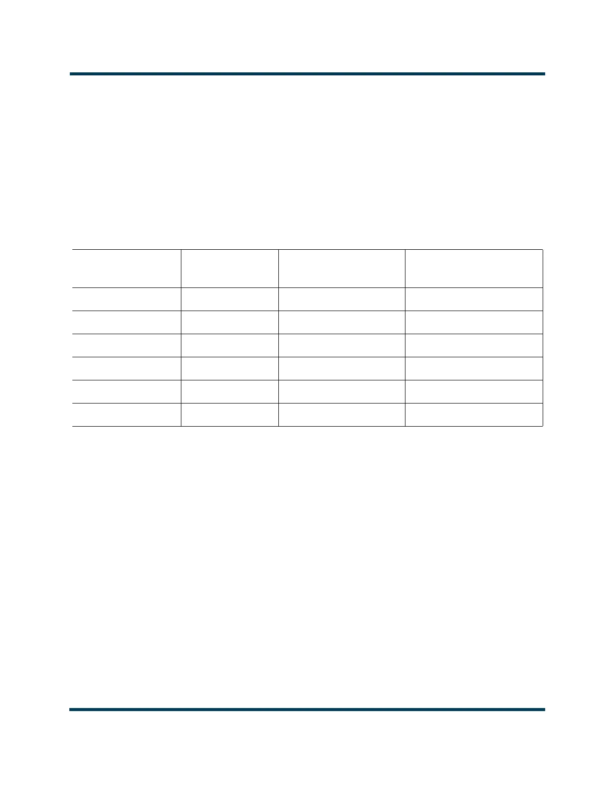
Table 1.5.1: VX Electrical Requirements
Typical line current values are based on maximum RF output power, nominal ac voltage (240 V ac) and typical efficiency.
The maximum inrush current value (per line) is present for half an ac cycle (between 8 and 10 ms). It is more than four times the typical
line current and is provided to aid in planning for upstream protection.
Observe local electrical codes when determining wire size and circuit breakers.
Nautel recommends that you base your wire sizes and breaker ratings on the typical line current for analog mode plus a nominal 25%.
TRANSMITTER
(FM MODE)
INPUT POWER
(VA)
AC SUPPLY
(V ac)
TYPICAL LINE CURRENT
(A)
VX150 350 1-Ph, 240 V ac (90-265) 1.5
VX300 400 1-Ph, 240 V ac (90-265) 1.7
VX600 940 1-Ph, 240 V ac (90-265) 3.9
VX1 1520 1-Ph, 240 V ac (185-265) 6.3
VX1.5 2500 1-Ph, 240 V ac (185-265) 10.4
VX2 3200 1-Ph, 240 V ac (185-265) 13.3
 Loading...


