18
ASSEMBLY
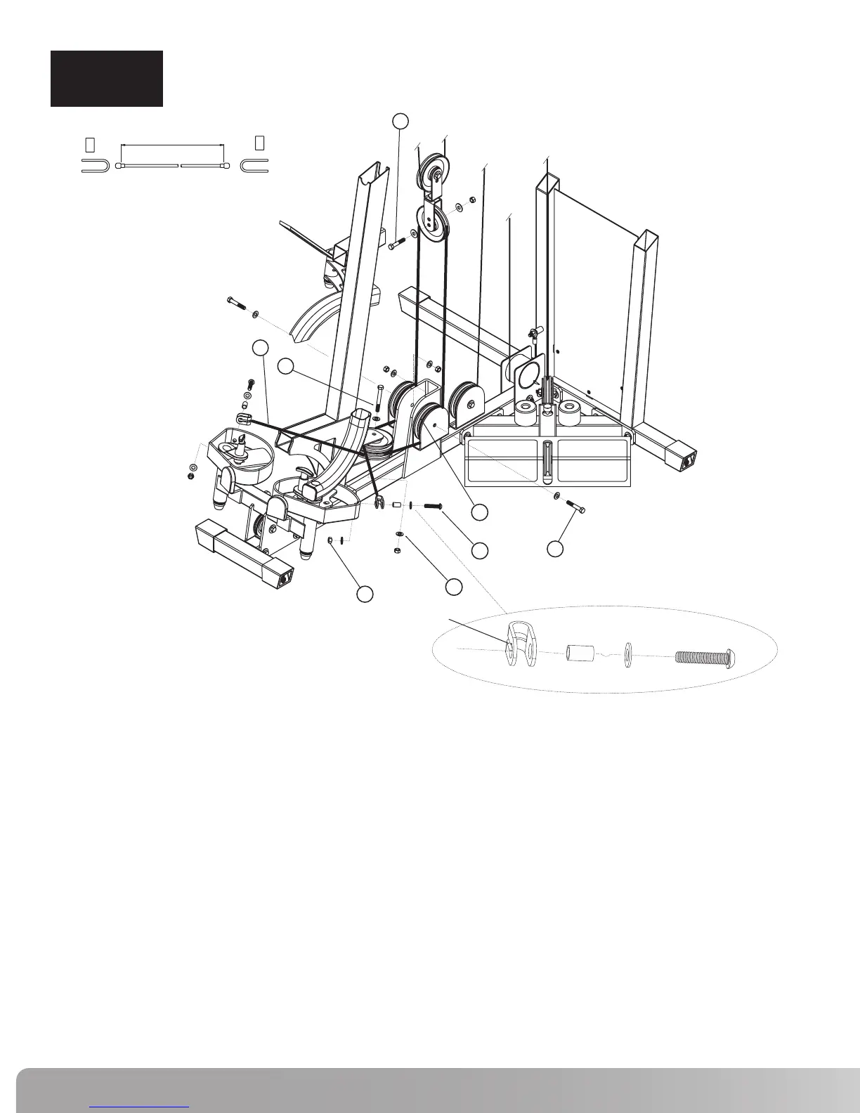
STEP 10
Step 10 Components:
Procedure:
# Component Qty
A.
Install two 4 1/2” Pulleys (45) in the lower bracket on the Front Upright Frame using the hardware
shown. Tighten hardware securely.
B. Attach Cable #4 (51) termination to the left Pec Fly Cam using the hardware shown. Be sure to place
the groove on the termination bracket against the Pec Fly Cam as shown in detail A.
Tighten hardware securely.
C.
Draw Cable #4 (51) around the top Pulley that was installed in step A.
D. Draw Cable #4 (51) around a 4 1/2” Pulley (45) and attach Pulley to the right side of the bracket on
the Main Base Frame using the hardware shown. Tighten hardware securely.
E.
Loop Cable #4 (51) around a 4 1/2” Pulley (45) and place in the Double Floating Pulley Bracket
shown. Attach Pulley to the inner hole of the bracket using the hardware shown. Tighten hardware
securely.
F.
Draw Cable #4 (51) around a 4 1/2” Pulley (45) and attach Pulley to the left side of the bracket on the
Main Base Frame using the hardware shown. Tighten hardware securely.
G. Draw Cable #4 (51) around the bottom Pulley that was installed in step A.
H. Attach Cable #4 (51) termination to the right Pec Fly Cam using the hardware shown. Be sure to
place the groove on the termination bracket against the Pec Fly Cam as shown in detail A. Tighten
hardware securely. NOTE: If cable termination does not reach the connection hole on the Pec Fly
Cam, adjust Pulleys (45) in the Double Floating Pulley Brackets (44) to increase the cable length.
45
51
58
61
62
67
71
73
4 1/2” Pulley
Cable #4 - Pec Fly (104.25”)
Hex Bolt 3/8” x 3”L
Hex Bolt 3/8” x 2 1/4”L
Hex Bolt 3/8” x 2”L
Button Head Allen Screw 1 3/4”L
3/8” Flat Washer
3/8” Lock Nut
5
1
1
2
1
2
12
6
67
61
73
71
58
45
51
62
2" L
2 1/4"L
1 3/4"L
3" L
104.25" (2650mm)
A
GROOVE
 Loading...