31
Note: Your machine may not match the image. For reference only.
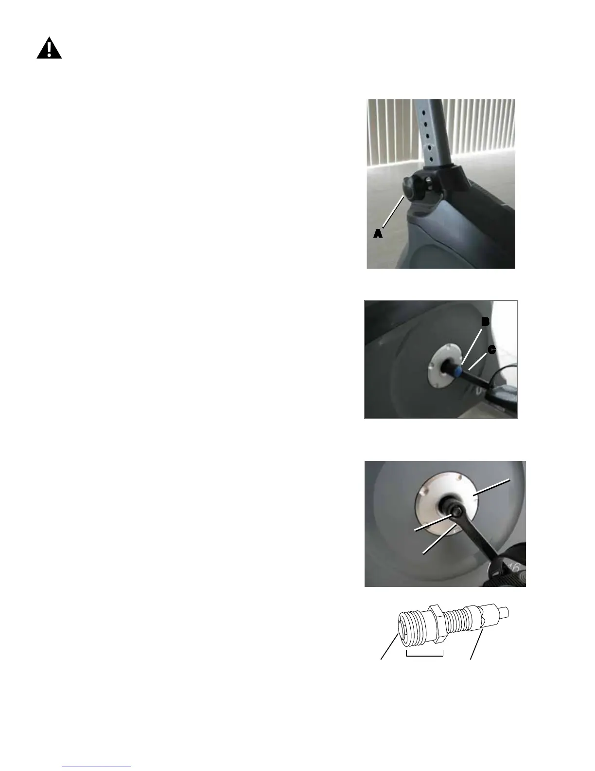
1. RemovetheSeatPostandtheSeatAdjustmentKnob(A).
Set them safely aside for reassembly.
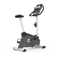
2. Usingaatheadscrewdriver,removethethreadedCap(B)
fromtheCrankArm(C)toexposetheHexHeadBolt(D).
3. Usingawrenchandsocket,removetheHexHeadBolt(D).
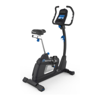
4. ThreadtheCrankPullerintotheCrankArm(C).Whenthe
CrankPullerisinthecorrectposition,only1-2threadsonthe
outer portion (CP2) of the Crank Puller should show.
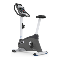
Note: Be sure the end of the Bolt (CP1) of the Crank Puller is
ushwiththeNut(CP2)asshown,beforeuse.
5. Using a wrench, turn the inner portion (CP3) of the Crank
Pullerclockwise.TheCrankArm(C)willslideoffasitis
tightened.
Go to Step 8.
6. Twist the Crank Cover (P) toward the front of the machine
to disengage the inner tabs. Carefully remove the Crank Covers
and set them safely aside.
Disconnect all power to the machine before you service it.
CP1 CP2 CP3
B
C
A
D
C
P