55
NOTICE: It is necessary to remove the Shrouds for this procedure. Refer to the “Replace the Shrouds” procedure.
It is necessary to adjust the Drive Belt tension at the end of this procedure. Refer to the “Belt Tension Adjustment” procedure
Note: Your machine may not match the image. For reference only.
1. Carefully remove the Shrouds. Refer to the “Replace the
Shrouds” procedure in this manual.
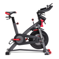
2. MarkthepositionoftheBeltTensioner(A)ontheMain
Frame bracket (D) to record the angle of the Tension Spring
arm’s position.
3. Slowly turn the Drive Pulley (B) backward and carefully
ease the Drive Belt (C) off the Drive Pulley to the outside.
Be sure to keep ngers clear of all pinch
hazards as you turn the Drive Pulley.
4. Using needlenose pliers, release the Tension Spring
(A1)fromthehook(H)ontheMainFrame.
5. Using13mmwrenchand6mmhexkey,loosenand
remove the Belt Tensioner Hardware (E). Remove the Belt
Tensionerassembly(A)fromtheMainFrameandtheDrive
Belt (C). Discard the old Belt Tensioner assembly.
6. InstallthenewBeltTensionerassembly.Adjustthe
Belt Tensioner position to the angle of the previous position
recorded in Step 2.
NOTICE: Do not overtighten the hardware (E). The
Belt Tensioner must be able to pivot. If the
hardware is too tight, this can cause wear on
the bearings.
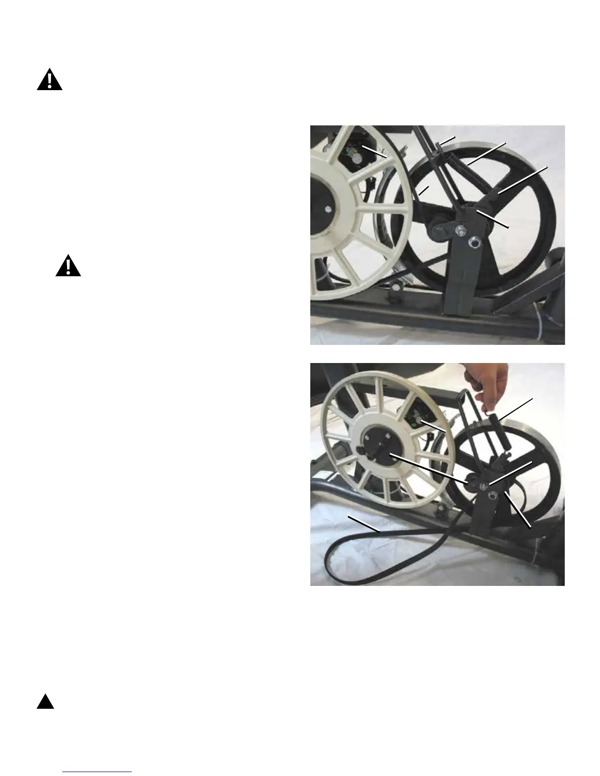
7. Put the Drive Belt (C) onto the Drive Pulley (B). Make
sure the Drive Belt is aligned on the Flywheel pulley (F),
BeltTensioner(A)andDrivePulley.Besurethattheupper
portion of the Drive Belt is under the bearings on the Belt
Tensioner.
8. Using needlenose pliers, attach the Belt Tensioner
spring(A1).Makesurethatthebelttensioniscorrect.Refer
tothe“BeltTensionAdjustment”sectioninthismanual.
Note: This step may require two people.
9. Final Inspection
Inspect your machine to ensure that all hardware is tight and
components are properly assembled.
!
Do not use until the machine has been fully
assembled and inspected for correct performance
in accordance with the Owner’s Manual.
Disconnect all power to the machine before you service it.
A
D
B
C
A1
H
E
A
C
F
B
A1
 Loading...