1-8
1. Introduction
AUDIO
AUDIO
AUDIO OUT
R
R/Cr
G/Y
B/Cb
V
H/
HV
R
L/MONO
R
L/MONO
R
L/MONO
L/MONO
SLOT 1 SLOT 2
DVI
RGB OUT
RGB 1
RGB 2
VIDEO S-VIDEO
3
8
12
4
56
7
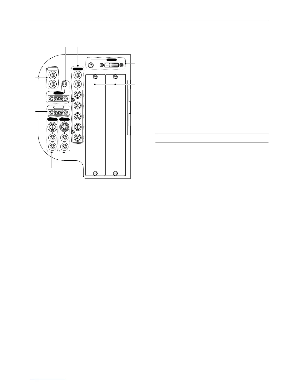
Terminal Panel Features
1. RGB 1 Connectors [R/Cr, G/Y, B/Cb, H/V, V] (BNC)
Connect R,G,B,H (Horizontal sync) and V (Vertical sync) out-
puts of external equipment.
If using a component with a combined sync (SYNC) output,
connect it to the H/V terminal. When using luminance and color-
difference signals of HDTV and DVD, connect Pr/Cr to the R, Y
to the G and Pb/Cb to the B input of the projector.
RGB 1 Audio Input Jacks (RCA)
L/MONO: This is your left channel audio input for stereo sound
coming from the RGB Input 1 source.
This also serves as your monaural audio input.
R: This is your right channel audio input for stereo sound from
the RGB Input 1 source.
2. RGB 2 Connector (Mini D-sub 15 Pin)
Connect your computer or other analog RGB equipment such
as IBM compatible or Macintosh computers. This also serves
as a component input connector that allows you to connect a
component video output of component equipment such as a
DVD player. This connector also supports SCART output sig-
nal. See page 2-9 for more details.
RGB 2 Audio Iput Mini Jack (Stereo Mini)
This is where you connect audio output from your computer or
DVD player connected to the RGB2 input. A commercially avail-
able audio cable is required.
3. DVI IN Connector (DVI-D 24 Pin)
This connector can be used to accept digital signal output from
a computer with a DVI connector.
DVI AUDIO Input Mini Jack (Stereo Mini)
This is where you connect the audio output from your com-
puter when connected to the DVI input. A commercially avail-
able audio cable is required.
4. RGB OUT Connector (Mini D-Sub 15 Pin)
You can use this connector to loop your computer image to an
external monitor from the RGB 1 or 2 input source.
5. VIDEO IN Connector (BNC)
Connect a VCR, DVD player, laser disc player, or document
camera here to project video.
VIDEO AUDIO Input Jacks R/L (RCA)
These are your left and right channel audio inputs for stereo
sound from a Video source.
6. S-VIDEO IN Connector (Mini DIN 4 Pin)
Here is where you connect the S-Video input from an external
source like a VCR.
NOTE: S-Video provides more vivid color and higher resolution than the tradi-
tional composite video format.
S-VIDEO AUDIO Input Jacks R/L (RCA)
These are your left and right channel audio inputs for stereo
sound from an S-Video source.
7. AUDIO OUT Jacks R/L (RCA)
You can use this connector to output sound from the currently
selected input source (RGB 1, RGB 2, DVI (DIGITAL), Video
or S-Video).
Output sound level can be adjusted in accordance with the
sound level of the internal speaker.
8. Slot 1/2
For optional RGB, SDI or DVI board.