7-4
z-3. Hookup
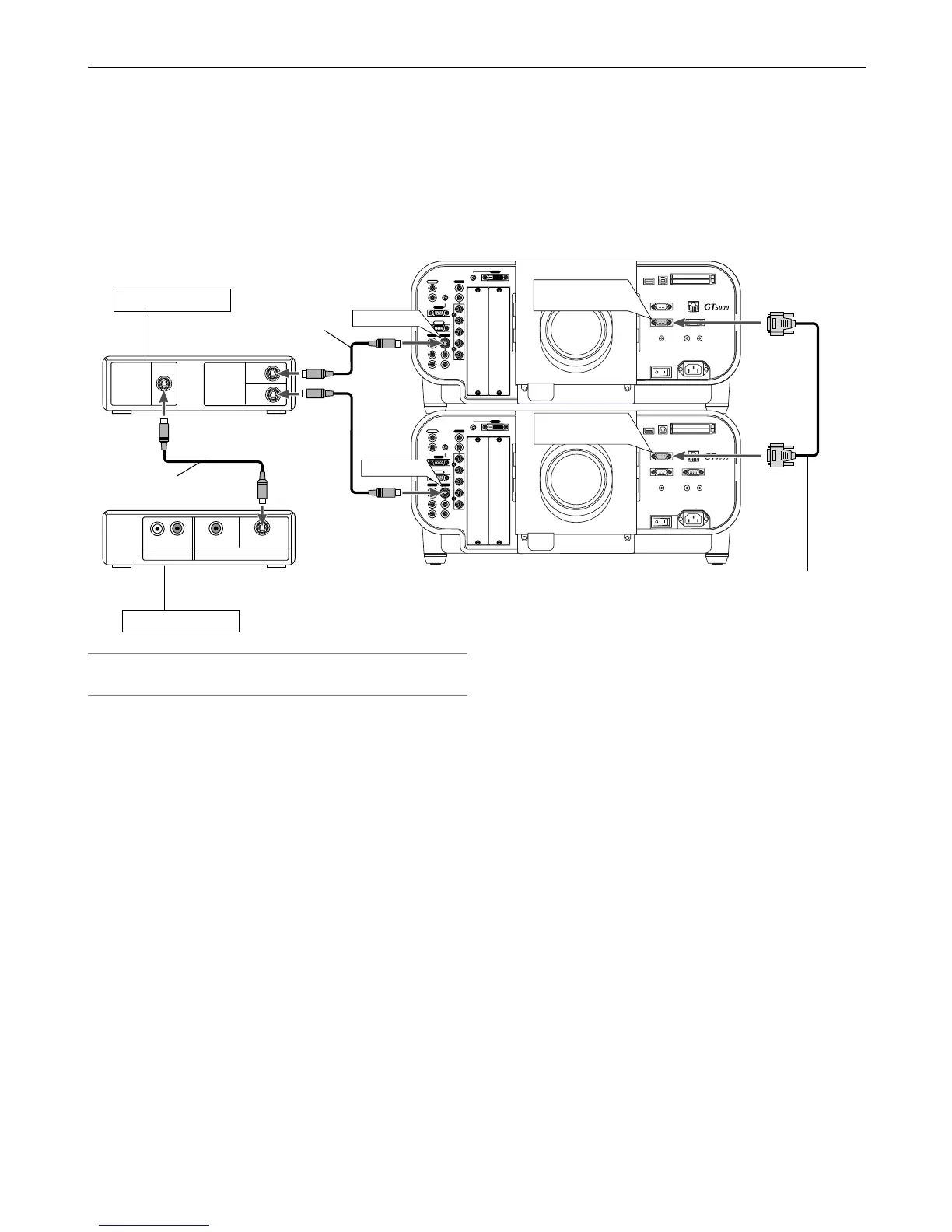
z-3-1. Use commercially available RGB signal cables to connect the RGB output of the master projector to the RGB input of the
slave projector until all the projectors are connected.
z-3-2. Next, using a commercially available, bi-directional RS-232C cable connect the PC CONTROL OUT terminal of the master
projector to the PC CONTROL IN terminal of the slave projector until all the projectors are connected.
z-3-3. Turn all the projectors on and roughly make some optical adjustments to each projector.
7. Setting Up for Double Stacking in Link Mode
USB(
MOUSE/HUB
) USB(PC) PC CARD
PC CONTROL
IN
IN
OUT
OUT
SC TRIGGER REMOTE 2
REMOTE 1
LAN
1
2
AC IN
AUDIO
AUDIO
AUDIO OUT
R
R/Cr
G/Y
B/Cb
V
H/
HV
R
L/MONO
R
L/MONO
R
L/MONO
L/MONO
SLOT 1 SLOT 2
DVI
RGB OUT
RGB 1
RGB 2
VIDEO S-VIDEO
USB(
MOUSE/HUB
) USB(PC) PC CARD
PC CONTROL
IN
IN
OUT
OUT
SC TRIGGER REMOTE 2
REMOTE 1
LAN
AC IN
AUDIO
AUDIO
AUDIO OUT
R
R/Cr
G/Y
B/Cb
V
H/
HV
R
L/MONO
R
L/MONO
R
L/MONO
L/MONO
SLOT 1 SLOT 2
DVI
RGB OUT
RGB 1
RGB 2
VIDEO S-VIDEO
2
1
S-VIDEO
S-VIDEO
OUTPUT
INPUT
AUDIO OUT VIDEO OUT
L R
S-VIDEO
VIDEO
S-VIDEO
S-VIDEO
PC CONTROL
OUT
PC CONTROL
IN
Bi-directional RS232C cable
(not supplied)
S-Video cable
(not supplied)
Distribution amplifer
Example: Composite signal
S-Video cable
(not supplied)
Video equipment
NOTE: Connect a commercially available distribution amplifier to both the master
and the slave projectors to distribute signal to two outputs of the master and the
slave projectors.