Installation Guide
QX-S5500G Series Ethernet Switches
1-3
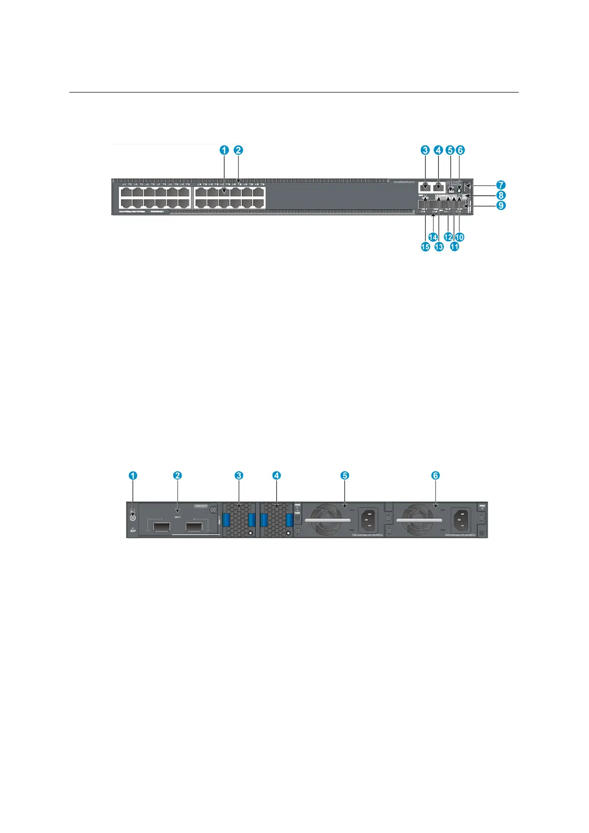
1.3 QX-S5524GT-4X1C panel views
Figure 1-5 QX-S5524GT-4X1C front panel
(1) 10/100/1000 BASE-T autosensing Ethernet port
(2) 10/100/1000 BASE-T autosensing Ethernet port LED
(3) Management Ethernet port
(5) USB mini Console port
(6) Port LED mode switching button
(8) System status LED (SYS)
(11) Interface card status LED (SLOT)
(12) Power module 2 status LED (PWR2)
(13) Power module 1 status LED (PWR1)
(15) Management Ethernet port LED
Figure 1-6 QX-S5524GT-4X1C rear panel
The QX-S5524GT-4X1C switch comes with power module slot 1 empty and power module
slot 2 installed with a filler panel. You can install one or two power modules for the switch as
required. In this figure, two PSR150-A1 AC power modules are installed in the power
module slots. For more information about installing and removing a power module, see
 Loading...