Installation Guide
QX-S5500G Series Ethernet Switches
3-15
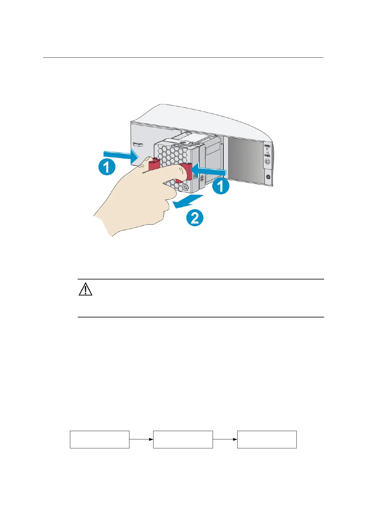
Figure 3-16 Removing a fan tray
3.6 Installing/removing a power module
CAUTION:
Provide a circuit breaker for each power module.
There is power supply module slot 2 on which power supply module slot 1 in the empty and
a blank panel were mounted with two power supply module slots for the
QX-S5524GT-4X1C, QX-S5548GT-4X1C or QX-S5524GP-4X1C. You can install one or
two power modules for the switch as needed. For more information about effective power
supply module, see "Appendix B FRUs and compatibility matrixes”
In power redundancy mode, you can replace a power module without powering off the
switch but you must strictly follow the installation and procedures in Figure 3-17 and Figure
3-18 to avoid any bodily injury or damage to the switch.
Figure 3-17 Installation procedure
Install the power
module
Connect the power
cord
Turn on the circuit
breaker
 Loading...