EasyManua.ls Logo

NEC QX-S5500G Series - Led; System Status LED

NEC QX-S5500G Series
161 pages
To Next Page IconTo Next Page
To Previous Page IconTo Previous Page
Loading...
Installation Guide
QX-S5500G Series Ethernet Switches
10. Appendix C Ports and LEDs
10-15
Pin
10BASE-T/100BASE-TX 1000BASE-T
Signal Specification Signal Specification
6
Rx-
Receive
BIDB-
Two directions B-
7
Non-data
-
BIDD+
Two directions D+
8
Non-data
-
BIDD-
Two directions D-
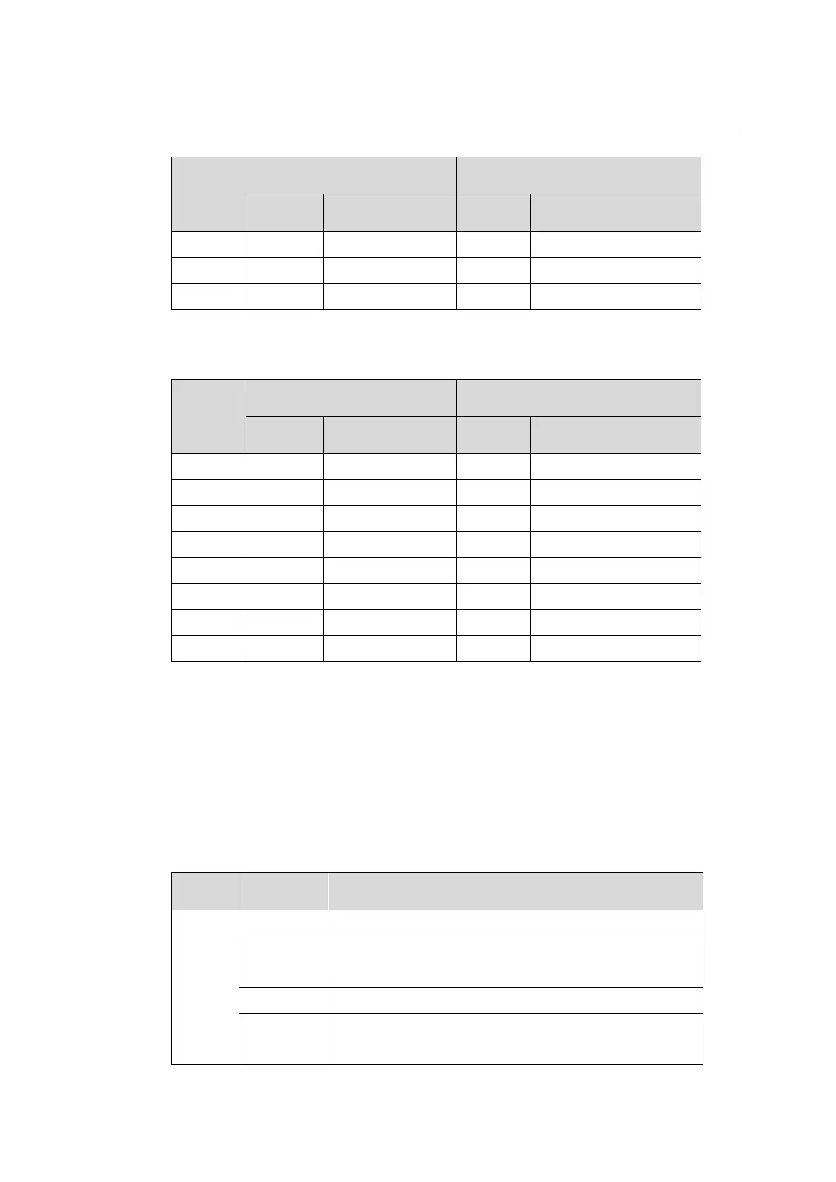
Table 10-13 Pin arrangement of MDI-X
Pin
10BASE-T/100BASE-TX 1000BASE-T
Signal Specification Signal Specification
1
Rx+
Receive
BIDB+
Two directions B+
2
Rx-
Receive
BIDB-
Two directions B-
3
Tx+
Transmission
BIDA+
Two directions A+
4
Non-data
-
BIDD+
Two directions D+
5
Non-data
-
BIDD-
Two directions D-
6
Tx-
Transmission
BIDA-
Two directions A-
7
Non-data
-
BIDC+
Two directions C+
8
Non-data
-
BIDC-
Two directions C-
10.3 LED
10.3.1 System status LED
System status LED shows the operating status of the switch.
Table 10-14 System status LED description
LED mark Status Description
SYS
Steady green
The switch is operating correctly.
Flashing green
(1 Hz)
The switch is performing power-on self test (POST).
Steady red
The switch has failed the POST or is faulty.
Flashing yellow
(1 Hz)
Some ports have failed to pass POST or are faulty.

Table of Contents

Related product manuals