QX-S5500 Series Ethernet Switches
3
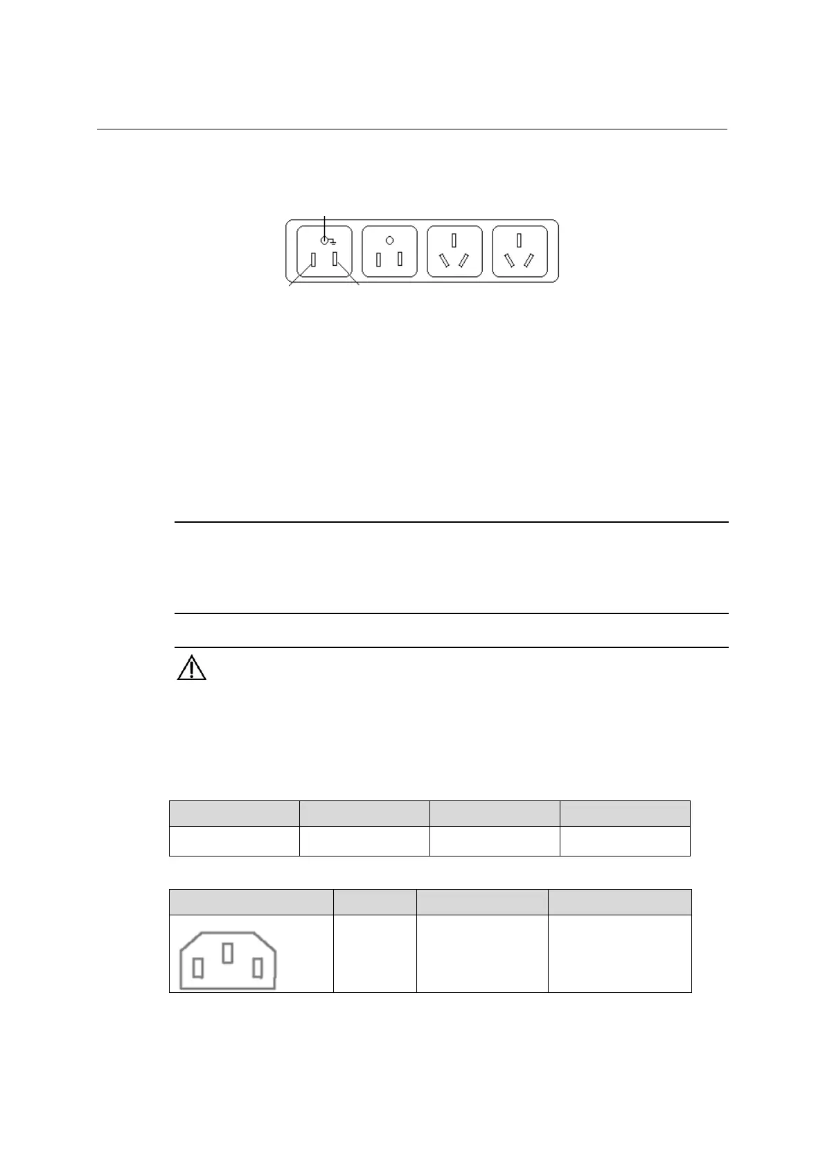
Figure 3-3 Power socket (recommended)
Neutral point
Zero line
Live line
Neutral point
Zero line
Live line
II. Connecting the AC Power Cable
1) Connect one end of the grounding cable to the grounding screw on the rear of the
chassis and the other end to the ground as near as possible.
2) Connect one end of the power cable to the power socket on the rear panel, and the
other end to the AC power supply.
3) Install the power cable retainer for the AC power cable. Insert the two ends of the
power cable retainer into the slots at both sides of the AC power socket, and then set
the power cable into the notch of the power cable retainer.
NOTE:
When connecting AC power cord to equipment, if light resistance is felt after cable insertion, please give
more a push and insert to the inside.
To make sure that the power cable won't be omitted, please install an AC cable retainer of an option.
WARNING:
Make sure that the ground wire has been properly connected before powering on the
switch.
Use the AC power cord which comply the standard of each country.
The socket-outlet shall be installed near the equipment and shall be easily accessible.
For the cables complying with our specifications, see Table 3-1, and Table 3-2.
Table 3-1 AC Input Power Specifications
Input Voltage Current (Max.) Phase Frequency (Hz)
100VAC, 120VAC,
220-230VAC, 240VAC
10A/5A Single 50/60
Table 3-2 Power Cable Specifications
Connector(on the Device Side) Cable Ratings Cable Length Plug(Power Facility)
125V, 10A
Comply the standard of
each country
Comply the standard of
each country
3-3
 Loading...