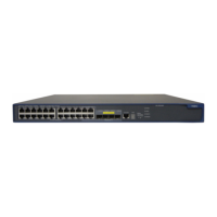
QX-S5500 Series Ethernet Switches
5
Network connection of the switch
Figure 5-3 Crossing cable
Crossover cable
white/orange
orange
white/green
green
white/orange
orange
white/green
blue
white/blue
green
white/brown
brown
1
2
3
4
5
6
7
8
blue
white/blue
white/brown
brown
1
2
3
4
5
6
7
8
IV. Pin arrangement
RJ-45 Ethernet interface is one of MDI (for routers and PCs) or MDI-X (for switches). Refer
to Table 5-2 and Table 5-3 about pin-out of RJ-45 Ethernet interface.
Table 5-2 Pin-out of RJ-45 MDI interface
Pin
10Base-T/100Base-TX 1000Base-T
Signal Function Signal Function
Line of bi-directional data A+
Line of bi-directional data A-
Line of bi-directional data B+
Line of bi-directional data C+
Line of bi-directional data C-
Line of bi-directional data B-
Line of bi-directional data D+
Line of bi-directional data D-
Table 5-3 Pin-out of RJ-45 MDI-X interface
Pin
10Base-T/100Base-TX 1000Base-T
Signal Function Signal Function
Line of bi-directional data B+
Line of bi-directional data B-
Line of bi-directional data A+
Line of bi-directional data D+
Line of bi-directional data D-
Line of bi-directional data A-
5-3

 Loading...