© by NECTA VENDING SOLUTIONS SpA
10
0210 206-00
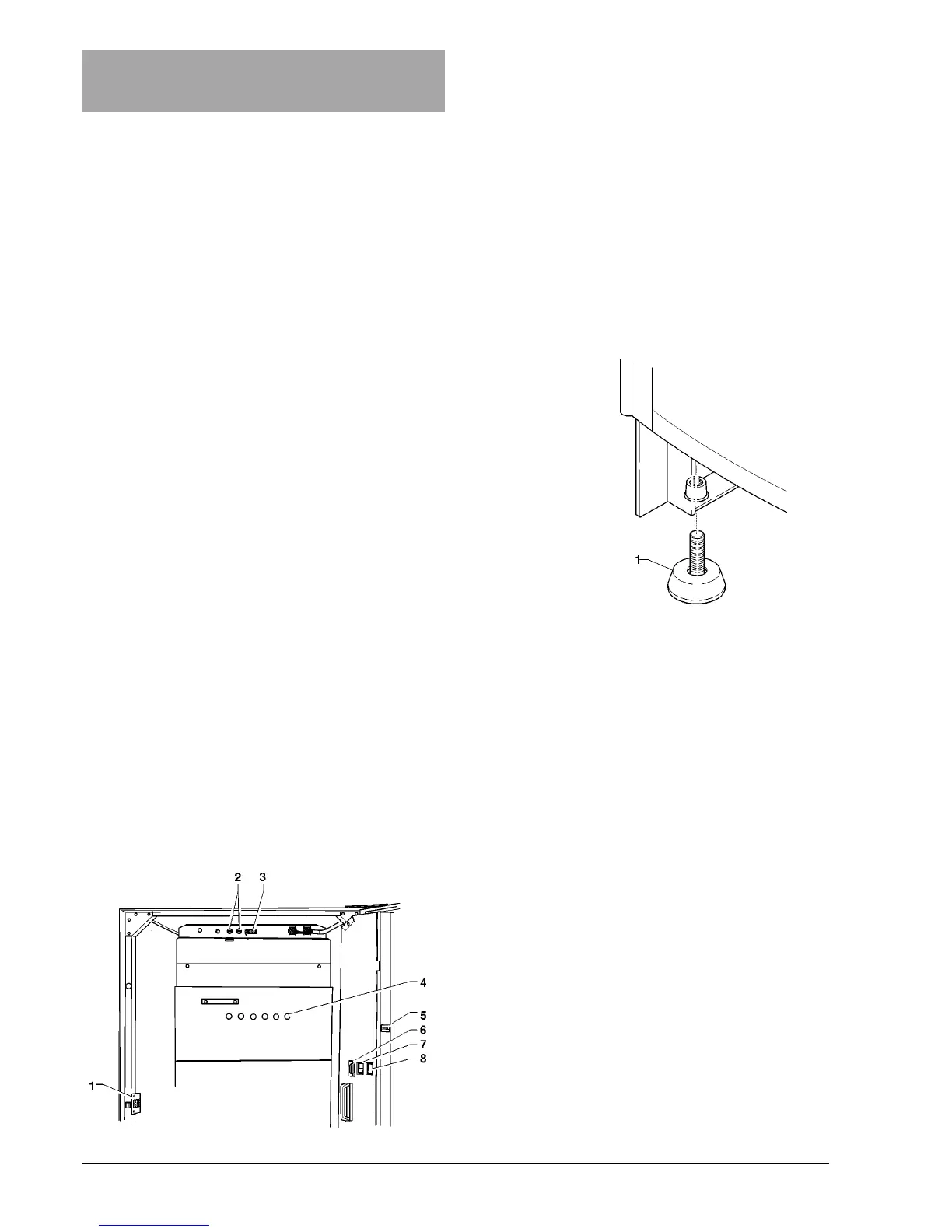
Fig. 12
1 - Adjustable foot
Installation and the following maintenance operations should
be carried out with the machine switched on and therefore
by qualified personnel only, who are trained in the correct
use of the machine and informed about the specific risks of
such situation.
The machine should be installed in a dry room where
the temperature remains between 2° C and 32° C.
At installation the hydraulic circuits and the parts in
contact with foodstuff should be fully sanitised to
remove any bacteria which might have formed during
storage.
DOOR SWITCH
When opening the door a special microswitch disconnects
the power from the machine electrical system.
To energize the system with the open door, simply insert
the special key into the slot (see Fig. 11).
With the door open there is no access to energised
parts. Inside the machine, the only parts that stay
energised are those protected by covers and carrying a
plate with the warning “Disconnect the power before
removing the protective cover”.
Before removing such covers disconnect the machine
from the power grid.
The door can be closed only after removing the key from the
door switch and lowering the machine top panel.
UNPACKING THE VENDING MACHINE
After removing the packing, check that the machine is not
damaged.
If in doubt do not use the machine.
No packing elements (i.e. plastic bags, polystyrene
foam, nails, etc.) should be left within the reach of
children, as they are potentially dangerous.
Packing materials must be disposed of in authorized areas
only, and all recyclable materials must be recovered by
specialised companies.
Important notice!!
The machine should be positioned with a maximum inclina-
tion of 2°.
If necessary provide proper levelling by way of the adjust-
able feet included (see Figure 12).
Chapter 2
INSTALLATION
Fig. 11
1 - Door switch
2 - Mains fuses
3 - Permanently live socket (230 V~ 2 A Max)
4 - Instant valves
5 - Mechanical counter
6 - RS232 serial port
7 - Mixer wash button
8 - Programming button
INSERTING THE PRODUCT LABELS
The labels indicating the available selections are supplied
with the machine and must be inserted into the special slots
at the time of installation, after removing the cover.
According to the model, some buttons may not be used
(refer to the selection dose table).