27
© by NECTA VENDING SOLUTIONS SpA 0210 206-00
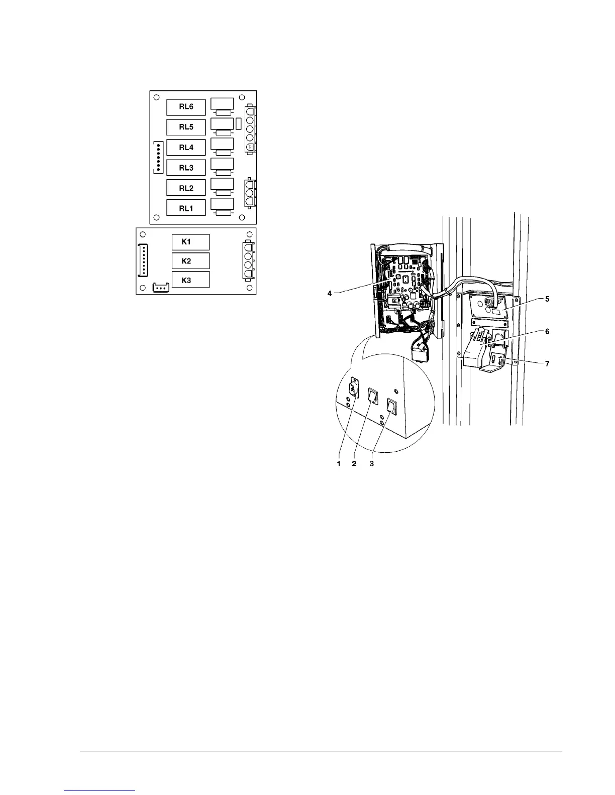
RELAY CARD
The 6 and 3 relay cards are controlled by the actuation
board and control some of the 230 V~ users.
Fig. 27
RELAY FUNCTION (see Wiring diagram)
RL1 = MFB MPF
RL2 = MD6 MDFB
RL3 = MF6
RL4 = MF7 MFFB
RL5 = MD7 MDFB
RL6 = MD8 MFB
K1 = LF (door)
K2 = MAS
K3 = EVT
BOILER CONTROL BOARD
This board (see Fig. 28) controls the instant boiler heating
element.
The coffee boiler is controlled by a similar board fitted on
the espresso module.
C.P.U. BOARD
The C.P.U. board (Central Processing Unit) controls all
power users available for maximum configuration and
processes the input signals from the push/button panel, the
payment system and controls the actuation board.
The LEDs, during the machine operation, give the following
indications:
- Green LED: blinks during normal operation of the C.P.U.
board
- Yellow LED: glows when 5 V DC is present
- Red LED: glows in the event of a software reset.
Fig. 28
1 - RS232 serial port
2 - Wash button
3 - Failure reset button
4 - C.P.U. board