© by NECTA VENDING SOLUTIONS SpA
26
0210 206-00
PRINTED BOARD FUNCTIONS
AND INDICATOR LIGHTS
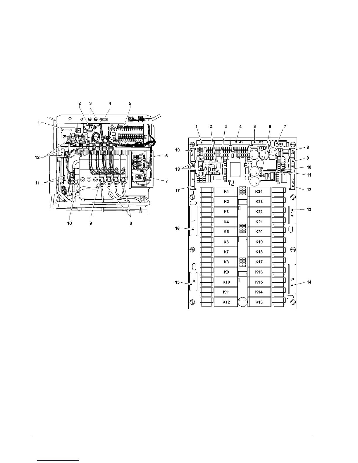
ACTUATION BOARD
This board (see Fig. 25) activates, by means of relays, the
230V~ components of the machine. It controls the signals
from the cams and/or microswitches fitted on the various
users. It also controls the boiler board and the relay
boards.
This board is powered with 24 V AC.
Fig. 25
The board control software is loaded directly onto the
microprocessor (through RS232).
- Green LED (2) blinking during the normal operation of the
board
- Yellow LED (6) indicating the presence of 5 V DC
- Red LED (3) glowing during the board reset
- Red LED (10) indicating the operating status of the
Espresso boiler heating element.
RELAY FUNCTION (see Wiring diagram)
K1 = EEA
K2 = MSB
K3 = MSCB
K4 = MDZ
K5 = MSP
K6 = ESC2 VENT
K7 = MSU
K8 = PM MF3
K9 = MD1
K10 = MF1
K11 = MD2
K12 = MF2
K13 = E1
K14 = E2
K15 = E3
K16 = E4
K17 = E5
K18 = E6
K19 = LF
K20 = MAC MD4 MDFB
K21 = ESC MD5 MFB
K22 = ERE MF5 MPF
K23 = M MD3 MDFB
K24 = MAC2 MF4 MFFB
1 - Transformer
2 - Instant boiler board
3 - Network fuses
4 - Permanently live socket
5 - Actuation board
6 - 6-relay card
7 - 3-relay card
8 - Instant prod. solenoid valves
9 - Boiler temperature probe
10 - Safety thermostat (manual reset)
11 - Anti-boiling thermostats (manual reset)
12 - Transformer fuses
Fig. 26
1 - Input signals
2 - Green LED
3 - Red LED
4 - Input signals
5 - Connector for board programming (RS232)
6 - Yellow LED
7 - Board power supply (24 Vac)
8 - Not used
9 - Probe and boiler control
10 - Red LED: Espresso boiler heating element
11 - Red LED: Instant boiler heating element
12 - 6-relay card connection
13 - 230 V~ users
14 - 230 V~ users
15 - 230 V~ users
16 - 230 V~ users
17 - 3-relay card connection
18 - "Can Bus" connection
19 - Not used