12
© by NECTA VENDING SOLUTIONS SpA 09-2003 228 00
COFFEE UNIT OPERATION
COFFEE DISPENSING CYCLE
After each time the machine is switched on, upon the first
espresso coffee based selection, the coffee unit is rotated
completely before the normal cycle, too ensure that the
device is in the correct start position.
When selecting coffee, the grinder is started and will
continue until the coffee doser chamber is full (see Fig.
14).
When the doser unit is full, the ground coffee dose is
released into the coffee unit.
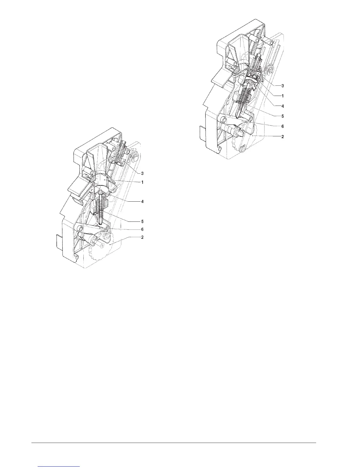
The coffee falls into the vertical brewing chamber (1) (see
Fig. 11).
The ratiomotor handle engaged with the disk (2) located
outside of the assembly rotates by 180°, making the
brewing chamber swing and lowering the upper piston (3).
Due to the water pressure, the pre-brewing spring (5)
sinks and the lower piston (4) goes down 4 mm, thus
forming a water cushion which allows an even use of the
coffee dose.
At the end of the dispensing cycle and during a pause of
3 seconds, the pre-brewing spring (5) will discharge the
water through the third way of the dispensing solenoid
valve, lightly pressing the used coffee dose.
By completing its rotation, the ratiomotor makes the
swinging lever (6) lift the pistons and the tea dose.
At the same time, when the brewing chamber returns to
its vertical position, the scraper on the coffee hopper stops
the used coffee dose and drops it.
The lower piston now returns to the bottom dead centre.
Fig. 11
1 - Brewing chamber
2 - External disk
3 - Upper piston
4 - Lower piston
5 - Pre-brewing spring
6 - Swinging lever
CHECKING AND ADJUSTING
THE MACHINE SETTINGS
To get the best results from the product used, the following
should be checked:
For coffee
That the used coffee dose is lightly compressed and
damp.
The grade of grinding of ground coffee.
The dose weight of ground coffee.
The dispensing temperature.
The water dose.
For instant products
The dose weight of the instant products.
The drink temperature.
The water dose.
Should the standard settings need to be changed, proceed
as indicated in the next sections of this manual.
The weight of instant products, the water dose and
temperature are directly controlled by the microproces-
sor.
To adjust them it is therefore necessary to follow the
programming procedures.
Fig. 12
1 - Brewing chamber
2 - External disk
3 - Upper piston
4 - Lower piston
5 - Pre-brewing spring
6 - Swinging lever