E-PAK 150 DX/300 DX/500 DXEN
30
Motor
power
(kW/hp)
Voltage
and
frequency
(V)/(Hz)
Nom.
current
(A)
F1
Recom.
mains
fuses,
slow (A)
F2 &
F3,
slow
(A)
F4,
slow
(A)
F5 &
F6,
fast
(A)
S1F Over-
load relay
setting
(A)
Min.
cable
area to
motor
(mm
2
) Z
Cable
area
inside
starter
(mm
2
) V
Cable
area
inside
starter
(mm
2
) X
3.45/5 230/60 12.6 25 6 4 1 12.6 2.5 2.5 2.5
3.45/5 440/60 7.7 15 6 4 1 7.7 2.5 2.5 2.5
3.45/5 460/60 7.3 15 6 4 1 7.3 2.5 2.5 2.5
3.45/5 575/60 4.95 15 6 4 1 4.95 2.5 2.5 2.5
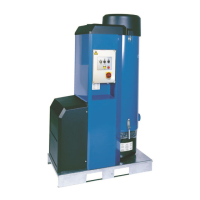
6 Main components
Figure 5 shows the main components of E-PAK 150 DX/300 DX/500 DX.
These are as follows:
1. Filter cleaning device.
2. Control lter.
3. Start and control unit and control panel.
4. Dust collector.
5. Vacuum limiting valve.
6. Thermal switch, 125 °C (257 °F), with automatic reset.
7. High-pressure side channel fan.
8. Pressure switch.
9. Outlet silencer.
10. Outlet.
11. Main lter.
12. Explosion relief panel (not on E-PAK 150 DX/300 DX/500 DX intended
for a suppression system).
NOTE! The explosion relief panel is to be handled with great care. Never
bend the membrane or frame.
13. Flanged inlet.
14. Collector bin with antistatic plastic bag.
NOTE! Never use the unit without the antistatic plastic bag! Use
Nederman original bags only.
15. Acoustic enclosure.
16. Detection device (suppression system only), see Figure 5b.
17. Action element (suppression system only), see Figure 5b.
6.1 Start and control unit
E-PAK 150 DX/300 DX/500 DX has a start and control unit, see Figure 10. For
information about the different terminals, see the terminal connection diagrams
in Figure 23 (E-PAK 150 DX) and Figure 24 (E-PAK 300 DX/500 DX).
NOTE! E-PAK 150 DX has a simplied start and control unit without Y/D
connectors and Y/D timer.
 Loading...