E-PAK 150 DX/300 DX/500 DXEN
32
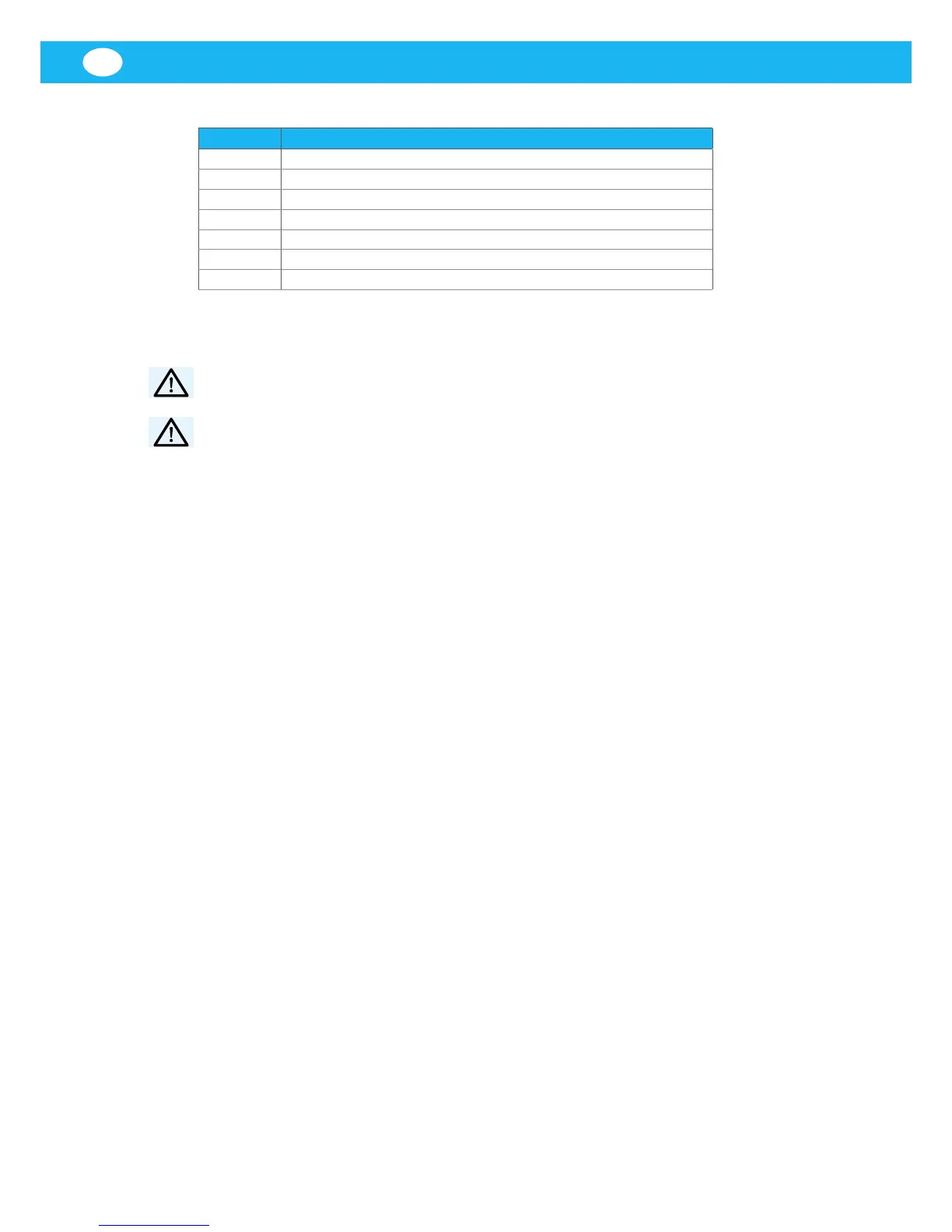
Table 6-1: Accessory terminals
Terminal Accessory/function description
1–2 Permanent 24 V AC of external equipment
3–4 Pilot signal
5–6 Remote start/stop
9–10 Compressed Air Switch (CAS)
11–12 External emergency stop
23–24 Remote run indicator
25–26 Remote alarm output (red fault indicator light)
7 Before installation
WARNING! Risk of personal injuries.
Always use proper lifting and protective equipment.
WARNING! Risk of tipping.
Consider the centre of gravity and attachments during transport.
NOTE! Always follow local regulations and legislation for all steps of the
installation process.
NOTE! Fill in the installation protocol during installation, see
‘Appendix A: Installation protocol’.
NOTE! Make a layout for the entire system before installing
E-PAK 150 DX/300 DX/500 DX.
7.1 Delivery checks
Check the unit for any transport damage. In case of damage or parts missing,
notify the carrier and your local Nederman representative immediately.
7.2 Installation requirements
7.2.1 Location and risk area
Prepare the location where E-PAK 150 DX/300 DX/500 DX is to be placed
before installation.
NOTE! E-PAK 150 DX/300 DX/500 DX needs approximately 1.0 m of free
space above the top to facilitate replacing of the main and control lters.
NOTE! Keep the area around the unit free to facilitate access to the collector
bin and control lter, see Figure 3.
7.2.2 Foundation
The unit is to be anchored to a hard, level and rm foundation, such as a
reinforced concrete foundation.
Consider the following when calculating the foundation or supporting
structure:
• The total weight of E-PAK 150 DX/300 DX/500 DX with accessories, see
Section ‘5.3 Technical and electrical data’).
• Traction forces generated by explosion relief venting, see Section 7.2.3
Bolts.
• Max. weight of the collected material.
 Loading...