FlexPAK 800/1000
EN
14
FlexPAK 1000
Relave humidity Max. 85% Max. 85% Max. 85%
Compressed air
6–10 bar (87–102 PSI) 6–10 bar (87–102 PSI) 6–10 bar (87–102 PSI)
Material recycling 93.6% per weight 93.6% per weight 93.6% per weight
* According to DIN EN/IEC 60335-2-69.
3.4 Fuses
Table 3-3: Fuses
Fuse Size Type
Main fuse F1, 230 V 65 A Slow mains fuses
Main fuse F1, 400 V 35 A Slow mains fuses
Main fuse F1, 460 V 40 A Slow mains fuses
Transformer, primary fuse F2 and F3
0,8 A* Slow fuses, 10.3×38
Transformer, secondary protecon PTC resistor
F4
50 mA* Fast, 5×20
F5
1 A* Slow, 5×20
* General size, see also the included electrical diagrams.
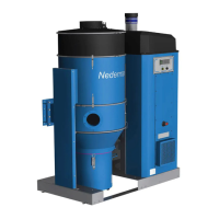
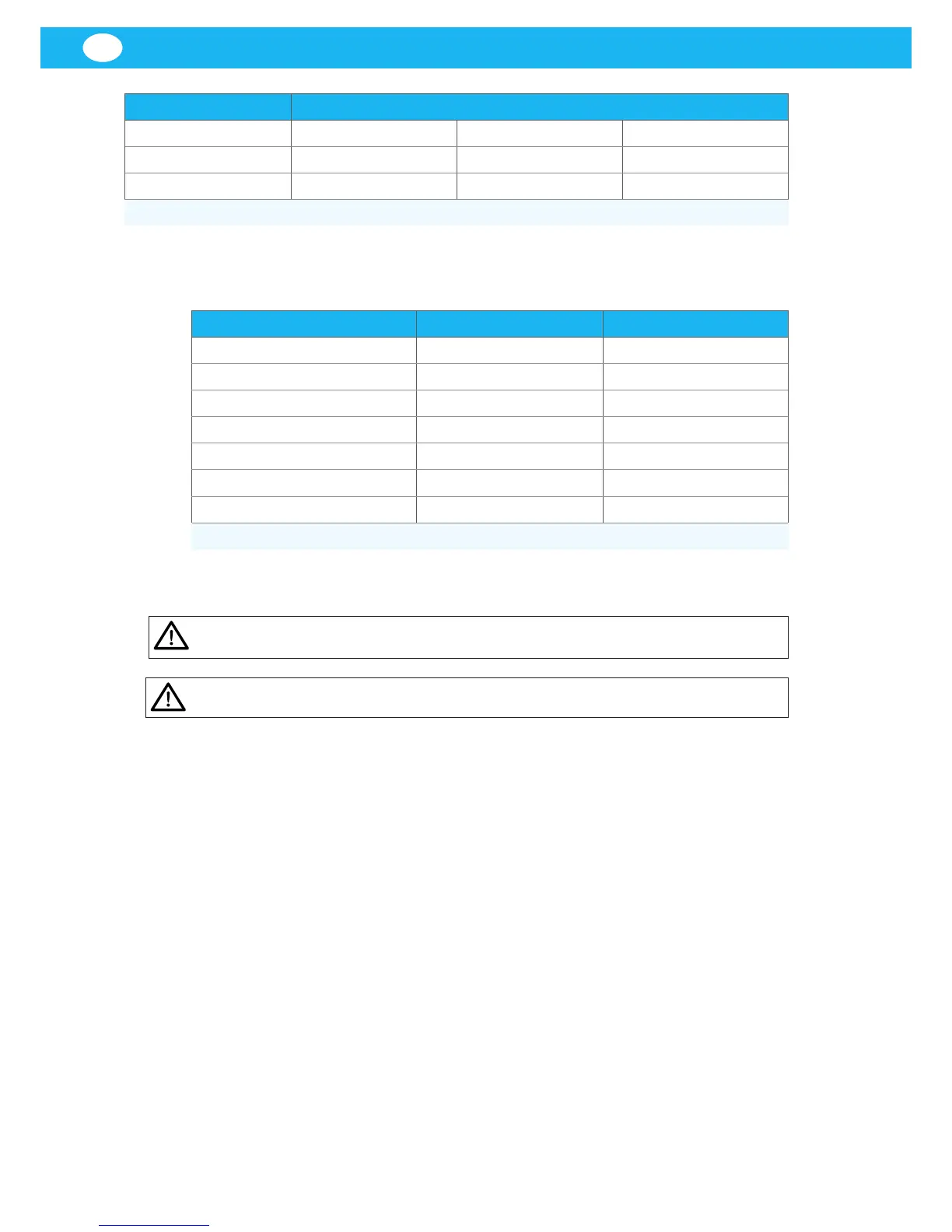
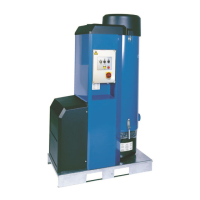
3.5 Main components
WARNING! Explosion risk.
Never use the unit without a plasc bag.
CAUTION! Risk of equipment damage.
Use only Nederman original spare parts and accessories.
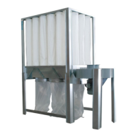
Figure 3, 4 and 5 show the main components of the unit:
1. Collector bin, see gure 3.
2. Dust extractor, see gure 3.
3. Texle lter bags, see gure 3.
4. Filter holder, see gure 3.
5. Filter Cleaning Valve (FCV), see gure 3.
6. Connecon duct from the dust extractor to the inlet silencer, see gure 3.
7. Start and control unit, see gure 3 and 4.
8. Control panel, see gure 3 and 4.
9. Emergency switch, see gure 3 and 4.
10. Frequency converter, see gure 3 and 4.
11. Frequency converter cooling air lter, see gure 3 and 4.
12. Cooling valve, see gure 3 and 4.
13. High pressure side channel fan, with pump characterisc, see gure 3 and 4.
14. PT100 sensor, see gure 4.
15. Outlet silencer aer fan, see gure 4 and 5.
16. Cooling air hose from the frequency converter cabinet, see gure 5.