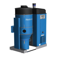
FlexPAK 800/1000
25
EN
7 Troubleshoong
For informaon on fuses, see Secon ‘3.4 Fuses’ and the included electrical diagrams.
There is no over current relay. The frequency converter parameter for maximum current is
adjusted from the factory and is not to be adjusted.
If a fault occurs which cannot be adjusted according to the following descripons, a
Nederman service technician is to be called.
7.1 Tools
To carry out troubleshoong, it is necessary to have a mulmeter with V DC and ohm
measuring capabilies.
7.2 Remove the lid of the start and control unit
Remove the lid as follows:
1. Unscrew the four plascs screws in the corner of the control cabinet.
2. Li of the lid.
3. Idenfy the PLC and the terminals in the boom of the cabinet.
Table 7-1: Trouble shoong guide
Error Possible cause Soluon
The unit
unexpectedly goes
directly into Running
mode when the
Standby/Running
buon is pressed.
• A valve at a workstaon is open
and its micro switch is acvated
• The PS cable is damaged with
its wires short-circuited
If the PS cable is damaged, press the Standby/Running
buon to put the unit into O mode and invesgate the
fault. If necessary, loosen the PS cable from the control
unit, see the electrical diagrams, and use an ohmmeter
across the leads in turn to locate the fault.
Defect PT100
temperature sensor.
Check whether the PT100 sensor is defecve as follows:
1. Disconnect the PT100 sensor wire from terminal 77 and
measure the resistance between terminal 78 and the
disconnected sensor wire.
2. Measure the resistance in the sensor using an
ohmmeter. The values in the table below are standard
values, so a deviaon from the measured value is
normal. If the averaged output (in ohm) deviates more
than ±2% from these values, the sensor will need to be
replaced.
Temperature (°C) Averaged output (ohm)
0 100
20 110
80 131
135 150
If the sensor has a resistance >150 ohm, there will be a
high temperature alarm. To check whether the sensor
input is working correctly, disconnect the PT100 wire at
terminal 77 and connect a jumper between terminals 77
and 78. Press the OK buon on the PLC to reset the alert.
If the alert disappears, the PT100 sensor input is working,
and the PT100 the sensor will need to be replaced.

 Loading...