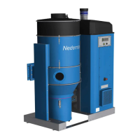
FlexPAK 800/1000
EN
20
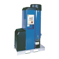
NOTE! Check that the supply voltage corresponds to the data on the machine plate of the
unit, see gure 1, before connecng the unit to the mains supply.
NOTE! Control that TR1, see gure 5, item 2, is connected to the correct voltage range.
NOTE! Always replace worn, faulty or defect electrical components with new original parts.
For the power circuit, control circuit and terminal connecon diagrams, see the electrical
diagrams that came with the unit.
5.6 General requirements
The following items are minimum requirements to ensure the proper funcon and
required level of protecon with regards to equipment category, the EC direcves and
standards listed in ‘Declaraon of conformity’:
• Take proper measures to avoid all types of electrical stray currents to and from the
duct system and electrical wiring.
• Check that the input voltage and frequency to the unit are correct.
5.7 Ground check measurement
Check that the unit is properly grounded aer both the main installaon and regular
maintenance work. If a component is removed and reed, ground connecon is to be
veried.
5.8 Automac bin emptying funcon
See the PLC sengs Manual.
5.9 Machining chips and swarf extracon
See the PLC sengs Manual.
5.10 Pneumac lter cleaning valve
See the PLC sengs Manual.
5.11 Compressed air installaon
WARNING! Risk of personal injury.
• Use ear protecon and safety goggles.
• The compressed air valve is to be locked in the closed posion during maintenance.
5.11.1 Requirements
NOTE! The specied air consumpon of the unit is limited to the short operaon of the
cleaning valve.
NOTE! Take measures necessary to avoid water or humidity in the compressed air when
the unit is installed in cold environments.
NOTE! If anfreeze addives are used, use them connuously. Once added, the removal of
the anfreeze addive may cause the pneumac components to malfuncon.