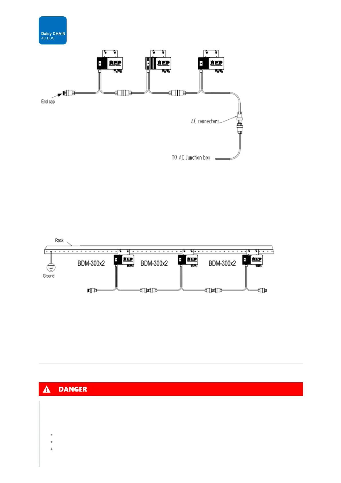
Typical Daisy Chain AC BUS Topology
STEP 4 – Ground the system
Each BDM-600 has an integrated ground protection circuit. The grounding wire is through the trunk cable, and should be
securely connected to the ground connector in the junction box.
STEP 5 - Ground the system through racking (option)
BDM-600 may also be grounded through the racking as shown below.
STEP 6 - Complete the connection map and connect the PV Modules
BDM-600 connection Map is a diagrammatic representation of the physical location of each BDM-600 in your PV
installation. The virtual array in NEP micro inverter gateway BDG-256 is created from the map you create.
Each BDM-600 has a removable serial number label located on the mounting plate. Enter this serial number into the BDG-
256, and correspond it to a number in the connection map.
DC Connection
Safety: Connecting DC
Danger to life due to electrical shock when live DC cables or components are touched
High DC voltages are present in the DC cables when PV modules are exposed to light. Touching live DC cables or
components may result in death or severe injuries due to electric shock.
DO NOT touch non-insulated parts or cables.
DO NOT touch live components when voltage sources are still connected or just disconnected.
DO NOT connect DC connectors to the product under load.