Connect PoE equipment in a business
environment
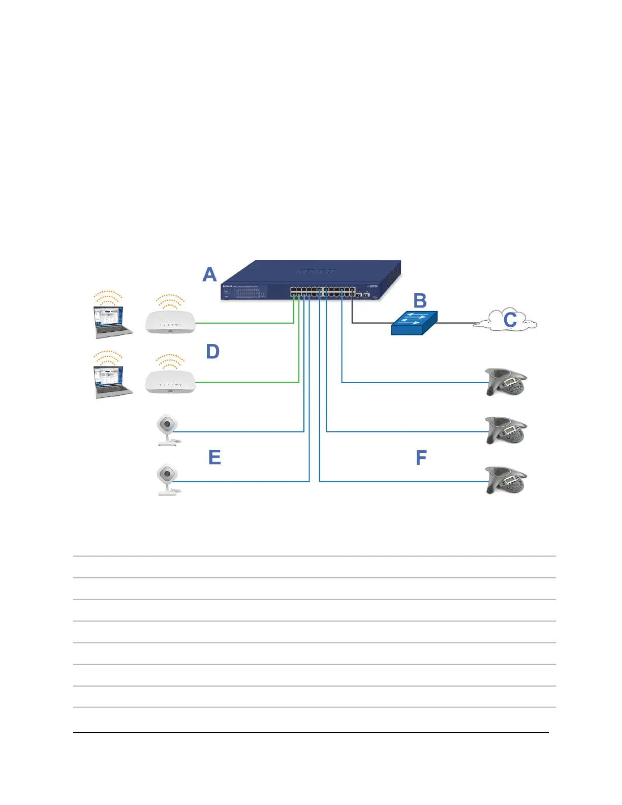
The following figure shows an example of how you can connect PoE WiFi access points,
PoE VoIP phones, and PoE surveillance equipment to the switch in a business
environment.
In a small office or home office network, the blue network icon represents a router that
is connected to an Internet modem. In such a setup, you must connect one port on the
switch to a LAN port on the router.
Figure 4. Sample PoE business use case
DeviceLetterDeviceLetter
PoE+ WiFi access pointsDSwitch model GS724TPv2A
PoE security camerasENetwork router or firewallB
PoE VoIP conference phonesFInternetC
ConnectionLine
1G connections to network devices and the InternetBlack
1G connections to PoE+ devices such as PoE+ WiFi access pointsGreen
1G connections to PoE devices such as security cameras and VoIP conference phonesBlue
Hardware Installation Guide21Applications
24-Port Gigabit (Hi-Power) PoE+ Ethernet Smart Managed Pro Switch with 2 SFP Ports
 Loading...