Hardware Installation
18
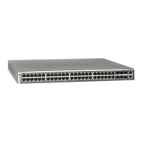
NETGEAR Managed Stackable Switch M5300 Series
For information about working with the CLI, see the Command Line Interface Reference for
the ProSafe M5300 Series Stackable Switches on the Resource CD that shipped with your
product.
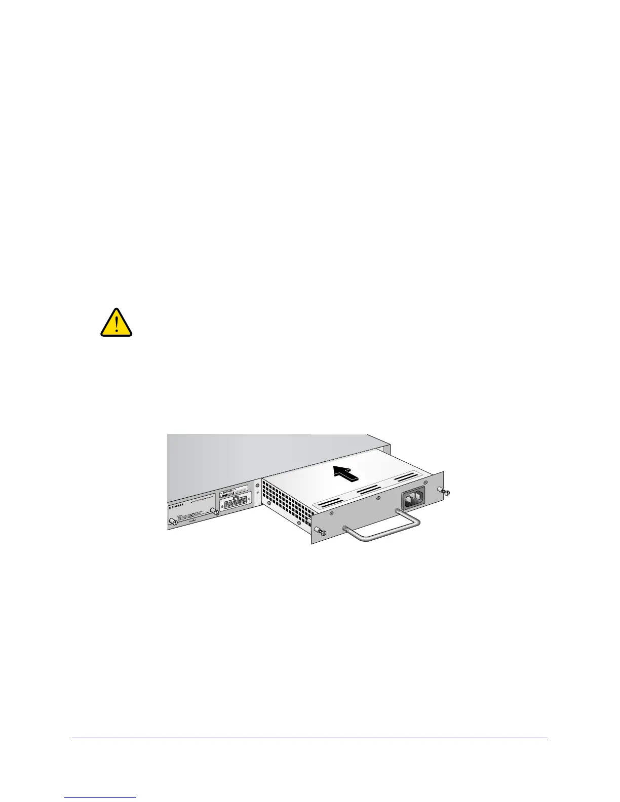
Power Module Bay
The power module bay provides an easy way to replace a failed power module APS135W or
APS525W. If the switch must continue to operate while you replace the power supply,
another APS135 or APS525 must be installed in the second power supply bay on the switch
rear panel.
Install a Power Module
To install a power module:
WARNING:
When inserting a power module into the switch, do not use
unnecessary force. Doing so can damage the connectors on the
rear of the supply and on the midplane.
1. Insert the new power supply module into the power module slot, and gently push the
module into the slot.
RPS Connector
2. Align the two captive screws with the screw holes in the switch rear panel.
3. Using a screwdriver
, gently tighten the captive screws.
4. Connect the power cord to the module and to an
AC-powered outlet.
Remove a Power Module
To remove a power module:
1. Disconnect the power cord from the power module.
2. Remove the power cord from the power connector
.
 Loading...