Introduction
7
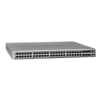
NETGEAR Managed Stackable Switch M5300 Series
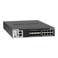
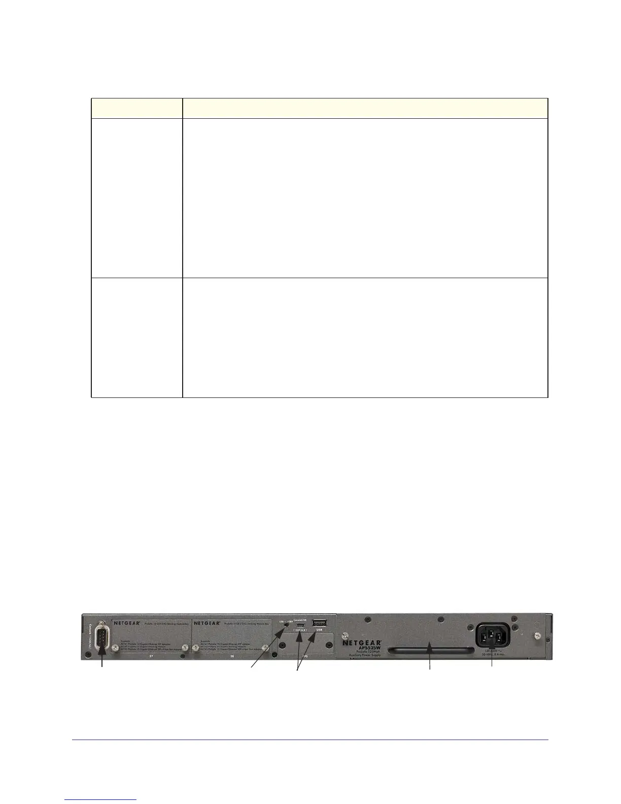
M5300 Series Rear Panel
The rear panel has a DB9 console port, a mini-USB console port, a USB host port, a
replaceable power supply, and an RPS interface. The IO module bays support any
combination of:
• ProSafe 10 Gigabit Ethernet XFP
Adapter (AX741)
• ProSafe 24 Gigabit Stackable Module (AX742)
• ProSafe 10 Gigabit Ethernet SFP+
Adapter (AX743)
• ProSafe 10 Gigabit Ethernet CX4
Adapter (AX744)
• Future adapter/module.
Replaceable
AC power
connector
power supply
Console
port
Console selection
switch
Mini-USB and USB
console ports
Figure 3. M5300 Series rear panel
10/100/1000M ports
(2 LEDs per port)
Link/ACT LED:
• Off: No link is established on the port.
• Solid green:
A valid link is established on the port.
• Blinking green:
The port is sending or receiving packets.
SPD LED:
• Off: No link or a valid link is established on the port.
• Solid yellow:
A valid 10/100 Mbps link is established on the port.
• Solid green:
A valid 1000 Mbps link is established on the port.
Note: If combo port media changes to fiber, the copper port LED
turns off.
SFP ports
(1 LED per port)
SPD/Link/ACT LED:
• Off: No SFP module link is established on the port.
• Solid Green:
A valid 1000 Mbps SFP module link is established on the port.
• Blinking Green: 1000 Mbps packet transmission or reception is occurring on the port.
• Solid Y
ellow: A valid 100 Mbps SFP module link is established on the port.
• Blinking Y
ellow: 100 Mbps packet transmission or reception is occurring on the port.
Note: If combo port media changes to copper, the SFP port LED
turns off.
Table 1. LED descriptions for M5300 Series switches (continued)
LED Description
 Loading...