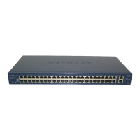
Power and Fan LEDs
Stack ID LED
Reset button
Factory Defaults button
Left LEDs: RJ45 SPD Mode LED
Right LEDs: nonfunctioning
USB port
SFP+ ports
Link/ACT LEDs
10G ports
Link/ACT LEDs
10/100/1000 Mbps ports
Physical Description
15
S3300 Smart Switch
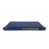
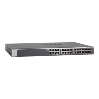
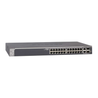
The following figures illustrate the front panel of models S3300-28X and S3300-28X-PoE+.
Figure 6. Front panel model S3300-28X
Power, Fan, and
Stack ID LED
Reset button
Factory Defaults button
Left LEDs: RJ45 SPD Mode LED
Right LEDs: PoE Mode LED
USB port
SFP+ ports
Link/ACT LEDs
10G ports
Link/ACT LEDs
10/100/1000 Mbps PoE ports
Max PoE LEDs
Figure 7. Front panel model S3300-28X-PoE+
The front panel provides the following components:
• Twenty four RJ-45 connectors for 10/100/1000 Mbps autosensing Gigabit Ethernet
switching ports
• Two 100M/1G/10GBASE-T copper ports (25–26) that you can also use for stacking
• Two 10G/1G SFP+ fiber ports (27–28) that you can also use for stacking
• One USB 2.0 port that supports FA
T32 and VF
AT file systems
• Reset button to restart the device
• Recessed Factory Defaults button to restore the device back to the factory defaults
• Link, Speed, and
Activity LEDs for each port and for the PoE model, PoE LEDs for
ports 1–24
• Power, Fan, and Stack ID LEDs; for model S3300-28X-PoE+ only, PoE Max LED
 Loading...


