vii
List of Figures
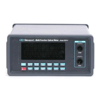
1. Model 2835-C Controller and Accessories .............................................. 1
2a. Model 2835-C VFD Display ....................................................................... 4
2b. Description of Model 2835-C Display Regions ........................................ 4
3. Front Panel Key Pad ................................................................................. 6
4. Decimal Point Indication of Menu Hierarchy Position ......................... 14
5. Rear Panel Power Supply Voltage Switches in Positions L, R ............. 23
6. Connecting a Detector with its Calibration Module ............................. 24
7. Model 2835-C Detector Calibration Module Input Port........................ 24
8. Measuring Laser Pulse Energy via a Thermopile in INTG Mode ......... 27
9. Model 2835-C Analog Signal Flow Diagram ........................................... 29
10. Model 2835-C Digitized Signal Flow Block Diagram .............................. 30
11. Thermopile Signals ................................................................................. 32
12. Energy Detector Signal from a Single Optical Pulse ............................. 33
13. Negative Baseline Drift Voltage to a Pulse Train .................................. 33
14. Time Varying Signal Measurements ...................................................... 34
15. Integrated Energy Via a Trapezoid Approximation ............................. 35
16. Measuring Laser Pulse Energy with a Thermopile ............................... 35
17. RS-232 Cable Connections ...................................................................... 42
Artisan Technology Group - Quality Instrumentation ... Guaranteed | (888) 88-SOURCE | www.artisantg.com

 Loading...