NEXPEED NBG440 User’s Manual
NexComm Systems, Inc. 13 PAGE
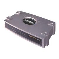
Connecting Cables and Connectors
This part explains the physical set up for NEXPEED NBG440 router. Connect the cable after
checking the connector in the rear side of NBG440 router.
Ground Connection Warning
The PROTECTIVE EARTHING CONDUCTOR or PROTECTIVE EARTHING
TERMINAL must be permanently connected to the equipment.
Connecting Power Cables
1> Connect one end of the power cable to the DC adapter.
2> Plug the other end of the power cable into the power terminal.
3> Plug the other end of the AC/DC power adapter into the port named "DC5V" in the
back of the NBG440 unit.
4> Power on the unit from the switch at the rear of the unit.
5> Confirm if the LED named PWR is turned on among the LEDs in the front panel.
Note: If the LED is not on, check if the power cable is properly connected or if the
power terminal is being supplied with the normal power.
Connecting LAN Port
1> Confirm if the UTP cable connector is a RJ-45 jack.
2> Connect one end of the UTP cable to the network equipment such as a cable or hub.
3> Connect the other end of the UTP cable to the port named "LAN" in the back of the
NBG440 unit.
4> Confirm if one of the LED named 1, 2, 3, 4 is turned on among the LEDs in the front
panel.
Note1: If the LED is not on, check if the UTP cable is properly connected or if there is a
disconnection in the UTP cable or if the RJ-45 jack is properly plugged in.
Note2: The LAN port is auto-MDI/MDIX capable; you can use either straight-through
or crossover cable to connect a network device (PC or Hub/Switch).
 Loading...