Page 24/79 GEO M10 HARDWARE SETUP PROCEDURE
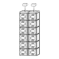
Angle splay setting sequences are as follow:
- GEO M1012 to GEO M1012: 0.6° (A) / 1.6° (B) / 3.2° (C) / 6.3° (D) / 9.5° (E) / 12.5° (F)
- GEO M1012 to GEO M1025: 12.5° (F) / 16° (G)
- GEO M1025 to GEO M1025: 16° (G) / 20° (H) / 25° (I)
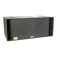
6.2.3 GEO M10 “Left” and “Right” configuration
GEO M10 can be installed “Left” or “Right”:
- “Left” means HF waveguide is left as seen from front
- “Right” means HF waveguide is right as seen from front
GEO M10 can be connected to bumpers “Left” or “Right” by simply flipping the cabinets.
Whenever possible, NEXO recommends symmetrical designs (preferably HF waveguide
inwards in stereo configurations)
GEO M10 “Left” GEO M10 “Right”
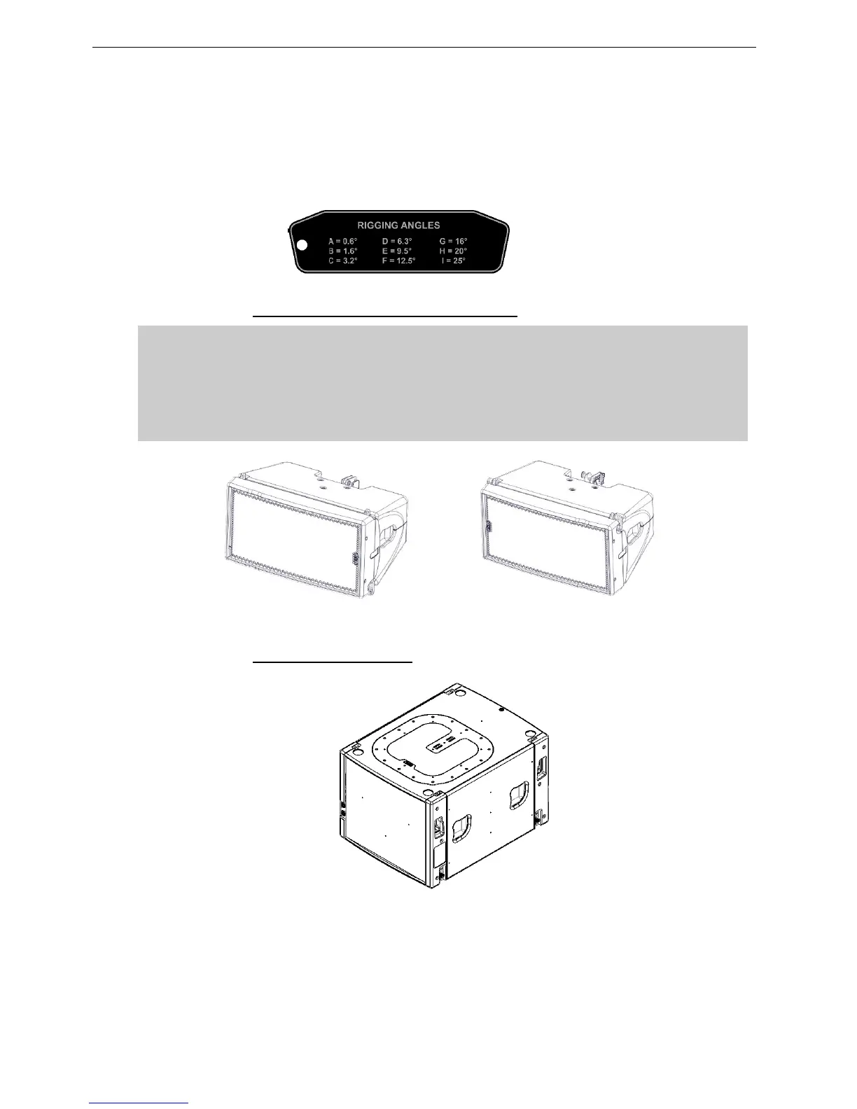
6.2.4 MSUB15 rigging system
 Loading...