GEO M10 HARDWARE SETUP PROCEDURE Page 37/79
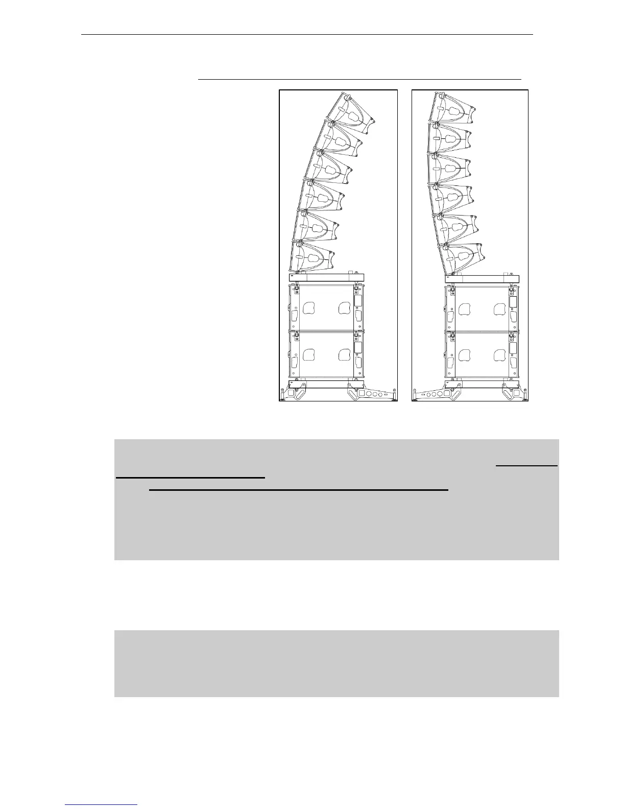
6.3.5 MSUB15 and GEO M10 on Touring Bumper with stacking extensions
Required item
- 2x VNT-BUMPM10
- 1 x VNT-GSTKM10S
- 1 x VNT-GSTKM10L
IMPORTANT
Ground stack assembly BUMPM10 + GSTKM10S + GSTKM10L is rated for a maximum of
2 x MSUB15 + 6 x GEO M10 in any inter cabinet angle configuration with +/-12° initial
angle, provided this device is assembled according to below rules:
- BUMPM10 must be adjusted to be horizontal
- Public is not allowed within a safety area which radius is equal or higher than
assembly height.
- It is highly recommended to secure the system to a fix point located at the back of the
stack.
Procedure
- Set the bumper on the ground so that front with front direction indicated by side arrows
- Insert GSTKM10L and/or GSTKM10S guides into bumper front and rear center slots
IMPORTANT
- If bottom GEO M10 initial angle is negative, GSTKM10L must be connected at the
front and GSTKM10S at the back
- If bottom GEO M10 initial angle is positive, GSTKM10S must be connected at the
front and GSTKM10L at the back
 Loading...